Quantcast
Channel: Cisco & Cisco Network Hardware News and Technology
Viewing all 278 articles
Browse latest View live

Cisco Catalyst 4500-X 10GE Modular Switch Review

$
0
0

Cisco Catalyst 4500-X Series Switches, the fixed 10GE aggregation switch, help you easily meet business growth objectives.

The Catalyst 4500-X series looks similar to the Cisco Nexus 5000 series switches, but actually it is definitely more of a campus LAN switch, rather than the Nexus data center line. There are two base configurations-a 16-port and a 32-port 10GE models. Each model has an expansion slot that currently supports an 8-port 10GE uplink model (Cisco datasheets suggest that a 40GE uplink module is on the roadmap).

NEW-CISCO-CATALYST-4500-X-10GE-MODULAR-SWITCH.jpg


Similar to the Nexus 5000s, the 4500-X ports support SFP+ 10GE optics along with 1GE SFP modules.The 4500-X supports both IPv4 and IPv6 routing in hardware, along with support for VRF-Lite and “Easy Virtual Network” (EVN) features. (The Nexus 5000s require an additional expansion module for layer 3 support).


VSS on Cisco 4500-X Series

The most intriguing feature in the 4500-X may be built-in VSS (“Virtual Switch System”) support. Two 4500-X switches can be linked by 10GE ports and configured as a single logical switch. This simplifies configuration while providing a higher level of availability. It also allows ether-channels to be be built across two switches (for link redundancy and performance while eliminating the need to build spanning-tree triangles). The VSS feature has previously been reserved for the 6500 chassis with Supervisor 720s. The 4500-X therefore offers a much more cost effective way to provide a highly available distribution layer (or even a core for smaller environments that want a 10GE backbone).

cat4500x-copy-1.png


The Cisco 4500-X is an intriguing new solution as an aggregation switch for campus LANs that want to bring in 10GE uplinks without the cost or complexity of a chassis based switch. VSS capabilities in particularly allow for a dual switch redundant solution that logically functions as a single switch—a solution that up until now has required a much more expensive chassis based switch.


Quick Look at the Specifications of Cisco 4500-X Switch

Total 1 Gigabit or 10 Gigabit Ethernet ports

Up to 40

Hot-swap Uplink Module

8 x 10 GE

Size

1 rack unit

Hot-swap, Redundant Power Supplies and Fans

Yes

System Power Consumption

~ 330 W

Integrated Services

Cisco Flexible NetFlow, Medianet, Cisco TrustSec

Reference from http://architechnic.net/architechnic/2012/3/6/new-cisco-catalyst-4500-x-10ge-modular-switch.html


More Related

Cisco Catalyst 4500-X Series Switch Family

Cisco 4500 VSS Requirement-Software, Hardware and Licensing

Cisco Catalyst 4500E Supervisor Engine 8-E Review

VSS on Cisco 4500/4500X Switches


Cisco Catalyst 6500 Series VSS 1440

$
0
0

VSS is network system virtualization technology that pools multiple Cisco Catalyst 6500 Series Switches into one virtual switch, increasing operational efficiency, boosting nonstop communications, and scaling system bandwidth capacity to 1.4 Tbps. Switches would operate as a single logical virtual switch called a virtual switching system 1440 (VSS1440). VSS formed by two Cisco Catalyst 6500 Series Switches with the Virtual Switching Supervisor 720-10GE

In a VSS, the data plane and switch fabric with capacity of 720 Gbps of supervisor engine in each chassis are active at the same time on both chassis, combining for an active 1400-Gbps switching capacity per VSS. Only one of the virtual switch members has the active control plane. Both chassis are kept in sync with the inter-chassis Stateful Switchover (SSO) mechanism along with Nonstop Forwarding (NSF) to provide nonstop communication even in the event of failure of one of the member supervisor engines or chassis. 


The Cisco Catalyst 6500 Series Virtual Switching System (VSS) 1440 allows for the merging of two physical Cisco Catalyst 6500 Series Switches together into a single, logically managed entity. The following figure graphically represents this concept where you can manage two Cisco Catalyst 6509 chassis as a single, 18-slot chassis after enabling Cisco Virtual Switching System.

Virtual-Switching-System-1440.jpg

The Cisco Catalyst 6500 Virtual Switching System (VSS) 1440 takes the flagship Catalyst 6500 platform to the next level with network system virtualization.

Virtual Switching System 1440 Redundancy State

Virtual-Switching-System-1440-Redundancy-State.jpg

Creating a VSS 1440

The key enabler of a VSS 1440 is the Virtual Switching Supervisor 720-10G. Any two Cisco Catalyst 6500 Series Switches with this supervisor engine can be pooled together into a VSS 1440*. The two switches are connected with 10 GbE links called Virtual Switch Links (VSLs). Once a VSS 1440 is created it acts as a single virtual Catalyst switch delivering the following benefits:

Operational Manageability

  • Two Catalyst 6500s share a single point of management, single gateway IP address, and single routing instance
  • Eliminates the dependence on First Hop Redundancy Protocols (FHRP) and Spanning Tree Protocol


Non-Stop Communications

  • Delivers deterministic, sub-200 millisecond layer 2 link recovery through inter-chassis stateful failovers and the predictable resilience of Etherchannel


Scales to 1.4 Tbps

  • Scales system bandwidth capacity to 1.4 Tbps by activating all available bandwidth across redundant Catalyst 6500 switches
  • Up to 132 ports of 10 GbE per system


What are the benefits of using VSS?

VSS offers superior benefits compared to traditional Layer 2/Layer 3 network design. VSS increases operational efficiency by simplifying the network, reducing switch management overhead by at least 50 percent. Single point of management, IP address, and routing instance,Single configuration file and node to manage and you won’t have to configure two switches with identical policies and other config. It eliminates the requirement for HSRP, VRRP or GLBP and you have to use just one IP address instead of three used with any FHRP.

Multi chassis Ether Channel (MEC) is a Layer 2 multipathing technology that creates simplified loop-free topologies, eliminating the dependency on Spanning Tree Protocol, which can still be activated to protect strictly against any user misconfiguration and with X2-10GB-ER 10 Gigabit Ethernet optics, the switches can be located up to 40 km apart.

Inter-chassis stateful failover results in no disruption to applications that rely on network state information (for example, forwarding table info, NetFlow, Network Address Translation [NAT], authentication, and authorization). VSS eliminates L2/L3 protocol reconvergence if a virtual switch member fails, resulting in deterministic subsecond virtual switch recovery.

By activating all available Layer 2 bandwidth across redundant Cisco Catalyst 6500 Series Switches with automatic, even load sharing. Link load sharing is optimized because it is based on more granular information, such as L2/L3/L4 parameters, unlike virtual LAN (VLAN)-based load balancing in Spanning Tree Protocol configuration.


More video about VSS

https://www.youtube.com/watch?v=RVwnXMVeKNs 

VSS on the 4500

https://www.youtube.com/watch?v=KUecqX1OIww


More Related

A Sample VSS Configuration for 2x Cisco Cat6500 with Supervisor 720

VSS on Cisco 4500/4500X Switches

Cisco 4500 VSS Requirement-Software, Hardware and Licensing

VSS Configuration on Cisco 6500

How to Activate Demo License on a Cisco 880 Router?

$
0
0

If you have a Cisco router 880 series with an advsecurity license but you find out your unable to use some protocols which you like to use. How to do that? In the following example that a Cisco 880 user shared here, and it told you how to activate Demo License on a Cisco 880 router?

I found out that the Cisco router 881w had an demo license of the advipsecurty license.

router#sh license feature

Feature name      Enforcement  Evaluation  Clear Allowed  Enabled

advipservices         yes         yes           yes         no

advsecurity           no          no            yes         yes


Which wasn’t actived. But your able to activate this license due the following command.

router#license boot module c880-data level ?

advipservices     advipservices level

advsecurity       advsecurity level


If you select the advipservices you will need to reboot the router. after the reboot the advipservices is activate now you have time to buy the correct license SL-880-AIS (upgrade option) [ Cisco 880 Advanced IP Services Image Feature License ]

You can download either also a demo license via the following linkhttp://www.cisco.com/web/go/license/index.html you need a CCO account to get the demo license.


If you have the correct license activated than you will see the following output

router#sh license feature

Feature name      Enforcement  Evaluation  Clear Allowed  Enabled

advipservices         yes         yes          yes          yes

advsecurity           no          no           yes          no


Now you have to restart the router and your new license should be activated.

Example case from http://glazenbakje.wordpress.com/2011/03/04/how-to-activate-demo-license-on-a-cisco-router-880-series/


More Related Cisco Licensing Topics

Cisco 800 Series Licensing Options

Cisco Licenses on Cisco ISR G2

General Features of Cisco ASA Licensing


How to Activate a Cisco License?

Cisco IP Phone: Exit Softkey does not Terminate Visual Voicemail Midlet

$
0
0

In this document it describes the current design and the problems with Visual Voicemail (when the phone is subscribed with Voicemail and Visual Voicemail) and offers a solution.


Problem

The application remains in the memory of the phone when you press the Exit softkey in Visual Voicemail. Therefore, when you press the Messages button, the phone displays the Visual Voicemail quickly. You can see the Visual Voicemail icon on the top left side of the screen.

See Additional User Information section in the Installation and Configuration Guide for Visual Voicemail


Complete these steps to reproduce the issue when the phone is subscribed with Voicemail and Visual Voicemail:

  1. Press the Messages button.
  2. Choose Visual Voicemail service between Voicemail (Standard TUI interface) and Visual Voicemail service.
  3. From the Sign In screen, press the Exit softkey before you sign in.
  4. Press the Messages button.
  5. The Sign In Screen is displayed instead of the Service Selection screen.


This particular issue is also seen when you log in to Visual Voicemail Service and use the Exit softkey.


This issue is seen on Skinny Call Control Protocol (SCCP) phones. Ideally the Exit softkey should teminate the application. The Visual Voicemail service will be terminated if the Messages button is used instead of the Exit SoftKey and both the options are presented when the Messages button is pressed again.


In the case of 99xx series phones, it shows both options even when the Exit softkey is used.


Solution

Complete these steps in order to resolve this issue:

  1. Add a new parameter in the Visual Voicemail service configured on Cisco Unified Communications Manager (CUCM).
  2. Name it as unload_midlet_on_exit and set it to 1.
  3. Resubscribe the phones to this service.
  4. Reset the phones.

Note: This might take a few minutes to load the service.

Solution from http://www.cisco.com/c/en/us/support/docs/unified-communications/unified-communications-manager-callmanager/117558-probsol-exitsoftkey-00.html


More Related Cisco IP Phone Topics

Two Smart Ways to Configure Cisco IP Phones

DHCP Option 150 & DHCP Option 66

How to Connect Cisco IP Phones?

How to Configure a Cisco Unified IP Phone 7921 with Call Manager Express?

Cisco to Update IP Phone Capabilities for Its Enterprise Users

EoS and EoL Announcement for the Cisco IP Phone 7921G Battery, Standard

$
0
0

Cisco announces the end-of-sale and end-of-life dates for the Cisco Unified Wireless IP Phone 7921G Battery, Standard. The last day to order the affected product(s) is March 2, 2015. Customers with active service contracts will continue to receive support from the Cisco Technical Assistance Center (TAC) as shown in Table1 of the EoL bulletin. Table1 describes the end-of-life milestones, definitions, and dates for the affected product(s). Table2 lists the product part numbers affected by this announcement. For customers with active and paid service and support contracts, support will be available under the terms and conditions of customers' service contract.

Table1. End-of-Life Milestones and Dates for the Cisco Unified Wireless IP Phone 7921G Battery, Standard

Milestone

Definition

Date

End-of-Life Announcement Date

The date the document that announces the end of sale and end of life of a product is distributed to the general public.

September 1, 2014

End-of-Sale Date

The last date to order the product through Cisco point-of-sale mechanisms. Theproduct is no longer for sale after this date.

March 2, 2015

Last Ship Date:
HW

The last-possible ship date that can be requested of Cisco and/or its contract manufacturers. Actual ship date is dependent on lead time.

May 31, 2015

End of Routine Failure Analysis Date:
HW

The last-possible date a routine failure analysis may be performed to determine the cause of hardware product failure or defect.

March 1, 2016

End of New Service Attachment Date:
HW

For equipment and software that is not covered by a service-and-support contract, this is the last date to order a new service-and-support contract or add the equipment and/or software to an existing service-and-support contract.

March 1, 2016

End of Service Contract Renewal Date:
HW

The last date to extend or renew a service contract for the product.

May 28, 2019

Last Date of Support:
HW

The last date to receive applicable service and support for the product as entitled by active service contracts or by warranty terms and conditions. After this date, all support services for the product are unavailable, and the product becomes obsolete.

February 29, 2020

HW=Hardware OS SW=Operating System Software App. SW=Application Software

Table2. Product Part Numbers Affected by This Announcement

End-of-Sale Product PartNumber

Product Description

CP-BATT-7921G-STD=

Cisco 7921G Battery, Standard


Product Migration Options

There is no replacement available for the Cisco Unified Wireless IP Phone 7921G Battery, Standardat this time.

Customers may be able to use the Cisco Technology Migration Program (TMP) where applicable to trade-in eligible products and receive credit toward the purchase of new Cisco equipment. For more information about Cisco TMP, customers should work with their Cisco Partner or Cisco account team. Cisco Partners can find additional TMP information on Partner Central at http://www.cisco.com/web/partners/incentives_and_promotions/tmp.html.

Customers may be able to continue to purchase Cisco Unified Wireless IP Phone 7921G Battery, Standard through the Cisco Certified Refurbished Equipment program. Refurbished units may be available in limited supply for sale in certain countries on a first-come, first-served basis until the Last Date of Support has been reached. For information about the Cisco Certified Refurbished Equipment program, go to: http://www.cisco.com/go/eos.

Service prices for Cisco products are subject to change after the product End-of-Sale date.

Cisco EoS and EoL News from http://www.cisco.com/c/en/us/products/collateral/collaboration-endpoints/unified-ip-phone-7900-series/eos-eol-notice-c51-732686.html


More Cisco EoS news you can visit: http://blog.router-switch.com/category/news/

Cisco ACI Mode

$
0
0

The Nexus 9000 family of switches will operate in one of two modes:

NXOS Mode–If you’ve worked with Cisco’s DC switches like the Nexus 7K or 5K, this should be very familiar to you. In this mode, you essentially have a 10GbE or 40GbE switch, with the features that are baked into that

In NXOS Mode, all of the additional custom ASICs that are present on the switch fabric are used primarily for enhancing the functionality of the merchant silicon platform, such as increasing buffer space, etc.

ACI Mode–This is a completely different mode of operation for the Nexus 9000 switch. In this mode, the switch participates in a leaf-spine based architecture that is purely driven by application policy. It is in this mode that we are able to define application relationships, and imprint them onto the fabric.


ACI is meant to provide that translation service between apps and the network.

Cisco-ACI.jpg

As mentioned before, also pointed out in the article Cisco Nexus 9000 Series Switches Overview, the second mode that the Nexus 9000 series operates in, is ACI mode. This mode allows for enhanced programmability across a complete fabric of Nexus 9000 switches. With ACI as the SDN solution on top, the fabric acts like one big switch–forwarding traffic using a myriad of policies that you can configure.

  • 1/10G Access & 10/40G Aggregation (ACI)

48 1/10G-T & 4 40G QSFP+ (non blocking)–meant to replace end-of-rack 6500’s

36 40G QSFP+ (1.5:1 oversubscribed)–used as a leaf switch, think end of rack

  • 40G Fabric Spine (ACI)

36 40G QSFP+ for Spine deployments (non blocking, ACI only)

1,152 10G ports per switch

  • 36 spine ports x 8 line cards=288 leaf switches per spine
  • Leaf switches require 40G links to the spine


The line cards that support ACI will not be released until next year.

Spine line cards

  • 36x 40G ports per line card and no blocking

Supervisor Modules

  • Redundant half-width supervisor engine
  • Common for 4, 8 and 16 slot chassis (9504, 9508, and 9516)
  • Sandy bridge quad core 1.8 GHz
  • 16GB RAM
  • 64GB SSD

System controllers

  • Offloads supervisor from switch device management tasks
  • Increased system resilience & scale
  • Dual core ARM 1.3GHz
  • EoBC switch between Sups and line cards
  • Power supplies via SMB (system management bus)

Fabric Extenders

  • Supports 2248TP, 2248TP-E, 2232PP-10G, 2232TM-10G , B22-HP, B22-Dell


Reference From http://keepingitclassless.net/2013/11/insieme-and-cisco-aci-part-1-hardware/


More Cisco ACI Mode Topics

Cisco ACI, What is It?

Cisco Nexus 9000 Series Switches Overview

Cisco 9500 Nexus Switch Overview-Model Comparison

The 8-slot Nexus 9508 Switch Review

More about Cisco 10GbE Optics Modules

$
0
0

There have been numerous different form factors and optics types introduced over the past years. The oldest, XENPAKs, remain very popular as the install base is large, while the newest SFP+ offer a much smaller form factor and the ability to offer 1G/10G combo ports on hardware for the first time. Like the move from GBIC to SFP the move from XENPAK to SFP+ seems inevitable, but currently there are several types of standard modules/form-factors available. In the following part there is a guide to these main module types and optical standards currently available.

XENPAK-the original 10GbE pluggable optics. Presents SC connectors

X2-the successor to the XENPAK. Presents SC connectors

XFP-the first of the small form factor 10GbE optics. Presents LC connectors

GBIC-the hot-swappable Gigabit Interface optical module with SC connector

SFP-also called mini-GBIC, is upgraded version of GBIC transceiver

SFP+-a 10GbE optics using the same physical form factor as a gigabit SFP. Because of this, many of the small SFP+ based 10GbE switches use 1G/10G ports, giving an added degree of flexibility. Presents LC connectors

Within these form factors are many different types of optical and electrical specifications; the only requirement is that the optics type match. It is perfectly acceptable to connect an X2 to an SFP, or a XENPAK to an SFP+, or any other combination.


Optical Standards

Electrical/Copper

10GBase-CX4
CX4 modules use Infiniband 4X cabling, and have a maximum distance of 15 meters. CX4 is an early copper standard, and due to the physical size of the connector, is not available in SFP+ form, or in XFP form from Cisco (Dell Networking, though, offers a CX4 XFP). CX4 was designed as a drop-in replacement for legacy Infiniband switching hardware – the existing Infiniband cable plant can be reused in a CX4 based network.

10GBase-CX1/10GBase-CU
10GBase-CX1 is the SFP+ copper standard. The standard has a maximum distance of 10 meters, though Cisco currently only offers lengths up to 5m. This is actually a cable with SFP+ ends, not a module with a separate cable.

Here is a picture

Cable-for-10GBase-CX1.jpg

Notice that the cable is permanently integrated into the SFP+ ends. Because of this, both devices must present SFP+ ports. While the cables are somewhat inconvenient to work with due to the integration, CX1 modules are used due to a very low cost, extremely low power consumption (0.25W per cable), and a negligible latency penalty.


Multimode Fiber

10GBase-SR
10GBase-SR is the original multimode optics specification, and is still by far the most commonly used. As it uses a single, low cost solid state laser assembly, it is also the least expensive of the optical modules available for a 10GbE platform. However, 10GBase-SR is very sensitive to fiber type. Below is a list of cable specs and maximum distance with SR optics.

Core Size
(microns)

Modal Bandwidth
(MHz*km)

Max
Distance

Notes

62.5

160

26m

This is standard multimode fiber.

62.5

200

33m


50

400

66m


50

500

82m


50

2000

300m

AKA: OM3 or 10GbE-optimized fiber


Because of this, it is highly recommended that any new deployment of multimode fiber be done with OM3 fiber. This will ensure an easier transition to 10GbE for future needs.

10GBase-LX4
To overcome the distance limitations of SR optics, the 10GBase-LX4 standard was developed. LX4 uses 4 lasers, each operating at a different wavelength, at a 2.5Gbps data rate. This results in a range of 240-300 meters, depending on cable grade. However, due to the complex laser assembly, it is not possible to get LX4 optics in XFP or SFP+ versions. With the ready availability of OM3 fiber and newer standards that provide long reach over multimode with a single laser, LX4 is rapidly becoming obsolete.

10GBase-LRM
The replacement to LX4, 10GBase-LRM will reach up to 220m over standard multimode fiber, but without the complexity of the LX4 optics. Instead, a single laser operating at 1310nm is used. This allows LRM optics to be packaged in XFP and SFP+ form factors.


Singlemode Fiber

10GBase-LR
10GBase-LR can reach up to 10km over singlemode fiber. There is no minimum distance for LR, either, so it is suitable for short connections over singlemode fiber as well.

10GBase-ER
10GBase-ER can reach up to 40km over singlemode fiber. Due to the laser power, attenuation is required for links less than 20km long.

10GBase-ZR
ZR optics can reach up to 80km over singlemode fiber. Due to the very high transmit power, significant attenuation is needed for shorter links. Use of ZR optics should be preceded with an optical power test of the fiber span in question to ensure a problem-free deployment. Interestingly, 10GBase-ZR is actually not an IEEE standard, though most vendors offer a ZR option.

10GBase-LW
10GBase-LW optics use the same laser, and have the same specifications as the 10GBase-LR optics. However, the LW optics present SONET/SDH physical signaling, allowing LW-equipped devices to interface directly with an existing OC192 transport infrastructure. LW optics are only available in XENPAK and X2 form factors. XFP-based cards move this functionality from the transceiver to the card itself, so make sure that if this functionality is needed, that the card itself has this support. The primary example is the as in the SPA-1X10GE-L-V2 vs the SPA-1X10GE-LW-V2.

10G over DWDM
With 10GbE, it is possible to get optics modules that output at DWDM wavelengths, allowing for much simpler DWDM deployments, and with these optics no additional transponder hardware is required. Current innovations in 10GbE/DWDM optics include full C-band tunability for ease of sparing, ordering, and provisioning of DWDM channels, as well as features like forward error correction (FEC) and OTN/G.709 support integrated directly onto the optic.


More about Cisco SFP, SFP+ Purchasing

Being used and interchanged on a wide variety of Cisco products, the hot Cisco SFPs can meet Cisco users’ different needs, for example, GLC-SX-MM, The 1000BASE-SX SFP, can support up to 1km over laser-optimized 50 μm multimode fiber cable; GLC-LH-SM, Cisco 1000BASE-LX/LH SFP transceiver module, operates on standard single-mode fiber-optic link spans of up to 10 km and up to 550 m on any multimode fibers; GLC-T over unshielded twisted pair (UTP) Category 5 Cable, etc. And module numbers, such as SFP-10G-SR, GLC-ZX-SM, SFP-GE-T, GLC-BX-D and so on. Cisco SFP+, the 10G fiber optical module, can connect with other type of 10G modules.  The popular SFP+ modules, for instance, SFP-10G-SR, used for high-speed data transmission applications, supports 300m by MMF; SFP-10G-LRM supports 220m on standard FDDI grade multimode fiber (MMF) and 300m on standard single-mode fiber (SMF, G.652); SFP-10G-LR, supports 10 km on standard single-mode fiber (SMF, G.652). And more detailed SFP, XEP, SFP+, GBIC modules and other Transceivers you can get from router-switch.com. It will offer you a good warranty and more free technical support. More info you can visit the page http://www.router-switch.com/Price-cisco-optics-modules_c8


More Cisco Optics Modules Topics

Cisco 10GBASE SFP+ Modules Overview

Cisco 10GbE Optics Modules & Optical Standards

Cisco Interface Cards for Cisco 1900, Cisco 2900 and Cisco 3900 Series

Why Should We Care About 10 Gigabit Ethernet Pluggable Optics?

Cisco XFP vs. SFP vs. SFP+

Cisco SFP vs. GBIC vs. XEP vs. SFP Plus

Cisco Indoor 802.11ac Access Point Comparison

$
0
0

In order to address these emerging trends, Cisco offers a new-generation of access points, the Cisco Aironet 3700, 3600, 2700, and 1700 for 802.11ac deployments Series, and the 3600, 2600, and 1600 Series. These access points extend spectrum intelligence, antenna density, and client acceleration to new price points in the mainstream. The product line also offers options that support the IEEE Wi-Fi standard, 802.11ac.

The second generation Cisco Aironet Access Point portfolio addresses a broad range of requirements for enterprise-class wireless services and provides industry-leading performance for secure and reliable radio-frequency (RF) connections. Whether you require entry-level wireless connectivity for a small enterprise, mission-critical coverage at thousands of locations, or best-in-class performance with investment protection for high-density environments, you can rely on Cisco’s broad access point portfolio.

The Aironet 2700 (3x4 MIMO) and 3700 (4x4 MIMO) are newer products and offer built-in support for 802.11ac via internal or external antennas, depending on the model.

The Aironet 2700 and 3700 are also slated to support the next generation Wave 2 module that will be released in the future as the development evolves. All three of these options are controller based (only) and support a wide selection of controller options.

Designed for small, medium-sized enterprise network, Cisco Aironet 1700 Series Access Points is entry-level access points that offes the latest 802.11ac Wi-Fi technology to meet the growing needs of today’s wireless network while providing offers the right value to help customers ease into 802.11ac networking.

The Cisco Aironet 1700 Series Access Points support 802.11ac Wave 1standard capabilities that allow you stay ahead of growing bandwidth requirements as:

• More wireless clients associate with the network

• More users tap into bandwidth-heavy multimedia applications

• Mobile workers increasingly use multiple Wi-Fi devices

The Cisco Aironet 1700 Series Access Points is a component of Cisco’s series of flagship, 802.11ac-enabled Aironet Series access points that deliver robust mobility experiences.

• Entry-level access point for small to midsized organizations, including retail, manufacturing, education, and branch offices

• Attractive price and performance for migrating to 802.11ac

• 802.11ac Wave 1 support with 3 x 3 MIMO, two spatial streams

• Cisco CleanAir Express spectrum intelligence across 20-, 40-, and 80-MHz-wide channels

• Optimized access point roaming which intelligently decides the correct access point as people move

• Multiple input, multiple output (MIMO) equalization for better uplink performance

The Cisco Aironet 2700 Series is a dual-band, 802.11ac supported Wi-Fi Access Point optimized for adding capacity and coverage to dense Wi-Fi networks. It also serves the performance needs of the latest BYOD clients now shipping with 802.11ac connections

 Delivering high performance for any small, medium-sized, and large enterprise network, the Aironet 2700 Series uses a purpose-built chipset with best-in-class RF architecture. It has been created specifically to take advantage of all the new speed and function of the latest Wi-Fi technology standard but at a price point that lets you ease into 802.11ac networking.

The main Feature Comparison of Cisco Aironet 802.11ac G2 Series Indoor APs

Aironet-170-2700-and-3700-AP.jpg

From Left to Right: 1700 Series vs. 2700 Series vs. 3700 Series

Cisco Aironet 802.11ac G2 Series Indoor Access Points

1700 Series

2700 Series

3700 Series

Wi-Fi standards

802.11 a/b/g/n/ac

802.11 a/b/g/n/ac

802.11a/b/g/n/ac

Ideal for

Small and midsize enterprises

Midsize or large enterprises that require advanced features

Midsize or large enterprises that require mission-critical traffic

Site type

Small and midsize offices, schools, warehouses

Midsize office, school or warehouse

Large office, midsize, or large warehouse

Application performance profile

802.11ac migration

High client density environments
802.11ac migration

High client density HD Video/VDI
802.11ac* migration
Comprehensive security

Future-proof modularity

N/A

N/A

Yes
WSM 
or 3G Small Cell 
or 802.11ac Wave 2* Module

Crowded areas


Yes

Yes

Number of radios

Dual (2.4 GHz and 5.0 GHz)

Dual (2.4GHz and 5.0GHz)

Dual (2.4GHz and 5.0GHz)

Max data rate

867 Mbps

1.3 Gbps

1.3 Gbps

MIMO radio design: spatial streams

3 x 3:2

3 x 4:3

4 x 4:3

Client count/ClientLink client count

200/-

200/128

200/128

Autonomous access point option

Yes

Yes

Yes

ClientLink 3.0

Transmit beamforming with 802.11ac clients

ClientLink 3.0, adding 802.11ac support for enhanced connectivity with 802.11 a/g/n/ac clients ECBF with 802.11ac clients 
ClientLink and ECBF to 11ac clients concurrently

ClientLink 3.0, adding 802.11ac support for enhanced connectivity with 802.11a/g/n/ac clients
ECBF with 802.11ac clients
ClientLink and ECBF to 11ac clients concurrently

CleanAir 2.0

CleanAir Express -- with 80 MHz channel support

Yes -- with 80 MHz channel support

Yes - 80 MHz channel support

GPS


Backhaul


DOCSIS3.0 capability


LTE Coexistence


VideoStream

Yes

Yes

Yes

BandSelect

Yes

Yes

Yes

Rogue access point detection

Yes

Yes

Yes

Adaptive wireless intrusion protection system (wIPS)

Yes

Yes

Yes

OfficeExtend
(Integrated- antenna models only)

Yes

Yes

Yes

FlexConnect

Yes

Yes

Yes

Power

802.3af, 802.3at PoE+, Enhanced PoE

802.3at PoE+, Enhanced PoE

4 x 4:3 operation: 802.3at PoE+, Enhanced PoE, Universal PoE (UPOE)
3 x 3:3 operation: 802.3af PoE

Temperature range

1700i: 0 to 40°C

2700i: 0 to 40°
2700e: -20 - 50° C
2700p -20 - 50° C

3700i: 0 to 40°C
3700e: -20 to 55°C
3700p: -20 to 55°C

Antennas

1700i: Internal

2700i: Internal
2700e: External
2700p: External

3700i: Internal
3700e: External
3700p: External

Limited lifetime warranty

Yes

Yes

Yes

*Planned for future support


More Related Cisco Wireless Access Points

New Cisco Aironet 2700 AP vs. AP3700

Connect with Aironet 700W Series Access Points

Cisco Aironet 1600 and 2600 Series Have Been Chosen to Replace Aironet 1140 Series and Aironet 1130 AG Series

How to Buy/Choose a Wireless Router for Your Home or Small-business Network?

Comparison of Cisco AP 2600 and Aironet 3600 Series

Cisco AP 3600 vs. Aironet 3500 Series

Cisco Aironet 1600/2600/3600 Series APs, Main Features and Comparison

Cisco Aironet 802.11n G2 Series Indoor Access Point Comparison


10 gigabit Ethernet /10 GbE Overview

$
0
0

Most companies these days are familiar with the 10 GbE technology. Why 10 GbE? Why 10 Gigabit Today? In the following part, we will share what the exact 10GbE is and more examples of using 10 GigE technology.


What is the Exact 10 GbE Technology?

10 gigabit Ethernet, a telecommunication technology, offers data speeds up to 10 billion bits per second. 10 gigabit Ethernet (10-Gigabit Ethernet) is also known as 10GE, 10GbE or 10 GigE.

The 10 GbE standard is fully interoperable with existing Ethernet protocols. It differs from traditional Ethernet in that it is a full-duplex protocol, meaning it does not need Carrier Sense Multiple Access/Collision Detection (CSMA/CD) protocols. In every other way, 10 GbE is the same as the original Ethernet protocol. This is important for network managers because as the demand for speed increases, 10 Gb Ethernet can easily be deployed within existing networks, providing a cost-effective technology that can support high-speed, low-latency requirements.

10-Gigabit Ethernet is often described as a disruptive technology that offers a more efficient and less expensive approach to moving data on backbone connections between networks. The IEEE 802.3ae standard permits distances between physical locations up to 40 kilometers over a single-mode fiber. Both single-mode and multi-mode fiber systems can be used with 10 GbE applications.

Similar to existing Ethernet protocols, 10 Gb Ethernet is a Layer 1 and Layer 2 protocol that adheres to key Ethernet attributes, including the Media Access Control (MAC) protocol, the Ethernet frame format, and minimum and maximum frame size. 10 Gb Ethernet connects current to fiber optic cable but is expected to be compatible with twisted-pair copper as well. The standard supports connections to both LANs and WANs, and can connect to SONET and SDH wide area networks.

Challenges to deploying 10 Gb Ethernet are primarily based on the costs to deploy versus the benefits received, along with issues associated with the potential replacement of legacy network technologies, such as point-to-point private lines and/or multiprotocol label switching (MPLS). 


For Many Companies & Enterprises, Why 10 Gigabit Today?

More for Less

In the past, 10GbE was neither necessary nor affordable. As with most burgeoning technologies, those dynamics are changing. Technological advancements have resulted in higher performance at lower costs. As such, gigabit and 10GbE bandwidth has become affordable for most companies.

Regardless of cost, there is also a distinct need. An increasing number of applications require considerable bandwidth to support the transfer and streaming of large data, video and audio files. As bandwidth-intensive applications and latency sensitive traffic types become ubiquitous, so does the need to support and transport them.

In addition, many companies are seeking tofuture proof” their network to ensure they can support emerging technologies and preserve their initial investments. In the past, fiber and wire cabling systems were installed with a 10-year lifespan in mind. However, with the rapid, ongoing evolution of network technologies, companies must be concerned with their current infrastructure’s ability to keep pace.

Costs associated with re-cabling a network can be exorbitant and organizations should take precautions to ensure their cabling systems can last well into the future. 10GbE provides the very best assurance for being able to support forthcoming technologies and delivers utmost investment protection.


Data Centers

For many institutions–especially those that utilize automated trading – uptime and response time is critical. Delays longer than a second can be exceedingly costly. With servers now being able to transmit near gigabit bandwidth and network downtime proving catastrophic, today’s enterprise data centers need extended bandwidth.

10GbE is an ideal technology to move large amounts of data quickly. The bandwidth it provides in conjunction with server consolidation is highly advantageous for Web caching, real-time application response, parallel processing and storage.


Campus Backbone Links

Many organizations wish to connect their campus buildings with high-speed links. Carrier-based services offload the burden of establishing and maintaining a 10GbE backbone, but limit flexibility and oftentimes prove too costly with expensive, unending monthly bills. This ongoing expense can be overwhelming for educational institutions, government organizations and hospitals as well as enterprises that do not have a set budget year to year.

Establishing a 10GbE campus backbone is a one-time expense that can provide significant cost savings when compared to monthly communications link bills.

Enterprise data center with 10GbE backbone

Enterprise-data-center-with-10GbE-backbone.jpg


Metro Area Transmission

Many companies also need to send and receive data beyond their campus, oftentimes in the form of large or streaming files that require high-speed links. Traditionally an area for carriers, 10GbE now offers an attractive alternative to costly monthly charges for long distance data transmission.

Many carriers offer expensive transmission services utilizing SONET OC-48 or OC-192c standards. These are considered “lit” services where a company has to add protocol conversion to be able to link from end to end.

Conversely, “un-lit” fiber–called Dark Fiber–is now being offered by carriers to companies able to provide their own connectivity. In these cases, routing switches supporting the 10GbE standard can provide their own transmission. Taking advantage of 10GbE performance in tandem with carriers’ Dark Fiber services can drastically reduce costs when compared tolit” transmission services.


About 10GbE Transceivers

IT professionals must also consider the devices that connect their cabling to their network. Transceivers provide the interface between the equipment sending and receiving data and the cabling transporting it. Just as there are distinct cabling technologies that coincide with distinct gigabit technologies, various transceivers are also available to match each gigabit standard.

Both gigabit and 10GbE technologies have “pluggable” transceivers. For gigabit technology, there are two defined transceiver types: Gigabit Interface Connector (GBIC) with its large metal case for insertion into low-density interface modules and units (switches), and the newer “mini-GBIC” or Small Form Factor Pluggable (SFP).

10GbE has four defined transceiver types. These transceivers are the result of Multi-Source Agreements (MSAs) that enable vendors to produce 802.3ae-compliant pluggable transceivers.

The four types are:

XENPAK–the first 10GbE pluggable transceivers on the market to support the 802.3ae standard transmission optics. They are large, bulky and used mainly in LAN switches. These transceivers are “hot pluggable” and support the new 802.3ak Copper standard with vendors now producing transceivers to connect CX4 cables.

XPAK–used primarily in Network Interface Cards (NIC) and Host Bus Adapter (HBA) markets for use in Servers and NAS devices.

X2the smaller brother of the XENPAK pluggable transceivers, the X2 form factor is about 2/3 the size of the XENPAK. With the same “hot pluggable” specifications and supporting all the 10GbE standards (including copper), the X2 form factor allows for more port density on switches. X2 is being used by ProCurve and Cisco thereby providing customers with a strong sense of assurance that this technology is the best choice for today and will have strong vendor support.

XFP–the newest pluggable transceiver on the market, XFP is the closest in size to the SFP pluggable transceiver now used for gigabit technology. Because it relies on a high-speed interface (10.3125Gbps), high-priced serializer/deserializer (SERDES) are required inside the switch to support it. Over time, the cost of such SERDES will decline, but today they add an unacceptable cost to the base system. Still, the positive aspect of the XFP form factor is it will allow switch vendors to increase port density in a smaller area for cost savings. A drawback of the XFP will be its inability to support the current Copper (802.3ak) or the 10GBASE-LX4 standards.

SFP+-As the industry brings down the cost and power of 10G optical devices, effort to increase the capacity of the existing SFP is being considered. For many customers, the possibility of achieving 10G speeds and a mechanical form factor that allows 1G or 10G to reside in the same footprint, might prove attractive. ProCurve continues to evaluate SFP+ as an alternative for the future.

As organizations grow their networks and support bandwidth-intensive applications and traffic types, 10GbE technology is becoming evermore pervasive. 10GbE functionality can provide immediate performance benefits and safeguard a company’s investment well into the future.

Just as there are many manifestations of the gigabit and 10GbE standards to suit various networking environments, there are also many copper and fiber cabling technologies to support them. Companies must have a solid understanding of not only their environment and need, but also the different standards and cabling technologies available to them. Doing so will help them develop a sound migration and cabling strategy, enabling them to reap the benefits of 10GbE for years to come.


More related Cisco 10GbE Transceivers

Catalyst 4500E & 4500X Series 10 GbE Review

About Transceiver & Cisco Transceiver Modules

Cisco XFP vs. SFP vs. SFP+

Cisco SFP vs. GBIC vs. XEP vs. SFP Plus

Cisco 10GBASE SFP+ Modules Overview

Cisco 10GbE Optics Modules & Optical Standards


Reference from http://searchnetworking.techtarget.com/definition/10-Gigabit-Ethernet and more...

CAT5 vs. CAT5e vs. CAT6

$
0
0

What is the difference between CAT5, CAT5E and CAT6 cable? Most people may be familiar with them. Because they are often used in computer networks, and also can be used to move data in home theatre applications. Category 5 (CAT5), Category 5E (CAT5E) and Category 6 (CAT6) cables are all twisted pair cables, available in solid and stranded varieties. What are their own features? In the following part, we will talk about the main difference between CAT5, CAT5e and CAT6.

Cable-comparison.jpg

Cat-5--Cat-5e-and-Cat-6.jpg

CAT5 cable is the most common, and comes in two types—Unshielded Twisted Pair, known as UTP, and Screened Twisted Pair, called SCTP. The SCTP cable has an extra shield to limit outside interference, and is generally only used in Europe. UTP cables are used all over the states and come either solid or stranded. Solid CAT5 cables are stiff and the best choice for long distance transmissions. Stranded CAT5 is bendier and is often used as patch cable. The standard amount a CAT5 cable can handle is 100MHz, with the option for 10 or 100 Mbps Ethernet. A CAT5 cable can also carry more than one signal—such as two phone lines and a single 100BASE-T channel in one cable.

utp-stp.png

CAT5e is very similar to CAT5,the ‘e’ standing for enhanced. This cable has more ability for data transmission, with the option to transfer data at 1000 Mbps. Cat5e can also be used with Gigabit Ethernet and generally has less near-end crosstalk, or NEXT than standard CAT5 cables. When installing a new system, CAT5e cables are almost always used over CAT5, though most existing installations are still CAT5.

The most sophisticated of the three cables is CAT6. Although it is also comprised of four pieces of twisted pair copper wire, it has a longitudinal separator. This allows the cables to be separated from each other and, in turn, allows not only for an increased data transfer speed, but less crosstalk and double the bandwidth. CAT6 cabling is a good choice for most new systems, especially those that are evolving and might need more options in the future. CAT6 is perfect for 10 Gigabit Ethernet and can work at up to 250 MHz. The really intelligent aspect of CAT6 is that it is compatible with already installed CAT5 and CAT5e cabling.

With the ever-changing landscape of technology, when you are installing a new system, the best choice for an easily adaptable future is CAT6. However, CAT6 is more expensive, and often some companies just don’t need anything quite that sophisticated. If you are just wanting to expand your network a bit, CAT5e is a more cost-effective and the simpler choice. CAT5, though perfectly adequate for many existing systems, will just not be able to keep up with the speed and performance needs of tomorrow.

Category 5 Network Cable

Bandwidth up to 100MHz

Supports 10/100 Ethernet (Ethernet and Fast Ethernet)

Category 5E Network Cable

Bandwidth up to 350MHz

Supports 10/100/1000 Ethernet (Ethernet, Fast Ethernet, and Gigabit Ethernet)

Backwards compatible with CAT5 cable

Reduced crosstalk compared to CAT5

Category 6 Network Cable

Bandwidth up to 550MHz

Supports 10/100/1000 Ethernet (Ethernet, Fast Ethernet, and Gigabit Ethernet)

Backwards compatible with CAT5/CAT5E cable

Reduced crosstalk compared to CAT5/CAT5E

CAT5E supports Gigabit networking, but CAT6 is certified for Gigabit networking and will perform better over longer distances. Keep in mind that your network is only as fast as your slowest component, so unless every piece of your network (routers, cables, etc.) supports Gigabit Ethernet, you will not be able to reach those speeds.


More Related Network Cable Topics

Cat5e and Cat6 Cabling for More Bandwidth? CAT5 vs. CAT5e vs. CAT6

Cat5e vs. Cat6 Cables

Cat5 vs. Cat5e

How to Create a Console Cable & Make a Console Connection?

How to Connect the Console Port to a PC?

How to Connect to a Cisco Standard Console Port (RJ-45)?

To Read about the Cisco Nexus 5548P Switch

$
0
0

Cisco Nexus 5548P Switch, the first platform in the Cisco Nexus 5500 Switches, is a one-rack-unit (1RU), 1 and 10 Gigabit Ethernet and FCoE access-layer switch built to provide 960 Gbps of throughput with very low latency. It has 32 fixed 1 and 10 Gigabit Ethernet ports that accept modules and cables meeting the Small Form-Factor Pluggable Plus (SFP+) form factor. One expansion module slot can be configured to support up to 16 additional 1 and 10 Gigabit Ethernet ports or 8 Fibre Channel ports plus 8 1 and 10 Gigabit Ethernet ports. The switch has a single serial console port and a single out-of-band 10/100/1000-Mbps Ethernet management port. Two N+N redundant, hot-pluggable power supplies and two N+N redundant, hot-pluggable fan modules provide highly reliable front-to-back cooling.

Cisco Nexus 5548P-

All ports are at the rear of the switches, simplifying cabling and reducing cable length. Cooling is front-to-back, supporting hot- and cold-aisle configurations that help increase cooling efficiency. The front panel includes status indicators and hot swappable, N+N redundant power supplies and their power entry connections and cooling modules. All serviceable components are accessible from the front panel, allowing the switch to be serviced while in operation and without disturbing network cabling.

Cisco Nexus 5548P Rear Panel

Cisco Nexus 5548P Rear Panel

Cisco Nexus 5548P Front Pane

Cisco Nexus 5548P Front Pane

The Cisco Nexus 5500 platform is equipped to support expansion modules that can be used to increase the number of 10 Gigabit Ethernet and FCoE ports or to connect to Fibre Channel SANs with 1/2/4/8-Gbps Fibre Channel switch ports, or both. The Cisco Nexus 5548P supports one expansion module from the following offerings:

• Ethernet module that provides sixteen 1 and 10 Gigabit Ethernet and FCoE ports using the SFP+ interface

Ethernet Expansion Module

Ethernet Expansion Module

• Fibre Channel plus Ethernet module that provides eight 1 and 10 Gigabit Ethernet and FCoE ports using the SFP+ interface, and 8 ports of 1/2/4/8-Gbps native Fibre Channel connectivity using the SFP interface

Combination Expansion Module

Combination-Expansion-Module.jpg

The Cisco Nexus 5548P control plane runs Cisco NX-OS Software on a dual-core 1.7-GHz Intel Xeon Processor C5500/C3500 Series with 8 GB of DRAM. The supervisor complex is connected to the data plane in-band through two internal ports running 1-Gbps Ethernet, and the system is managed in-band, or through the out-of-band 10/100/1000-Mbps management port. Table 1 summarizes the control-plane specifications.

Cisco Nexus 5548P Control Plane Components

Component

Specification

CPU

1.7 GHz Intel Xeon Processor C5500/C3500 Series

(dual core)

DRAM

8 GB of DDR3 in two DIMM slots

Program storage

2 GB of eUSB flash memory for base system storage

Boot and BIOS flash memory

8 MB to store upgradable and golden image

On-board fault log

64 MB of flash memory to store hardware-related fault and reset reasons

NVRAM

6 MB of SRAM to store syslog and licensing information

Management interface

RS-232 console port and 10/100/1000BASE-T mgmt0

The Cisco Nexus 5548P is equipped with seven UPCs: six to provide 48 ports at 10 Gbps, and one used for connectivity to the control plane. Figure 6 shows the connectivity between the control plane and the data plane.

Cisco Nexus 5548P Data Plane and Control Plane Architecture

Cisco-Nexus-5548P-Data-Plane-and-Control-Plane-Architecture.jpg


More details about Cisco Nexus 5500 and Nexus 5548P you can read her http://www.cisco.com/c/en/us/products/collateral/switches/nexus-5548p-switch/white_paper_c11-622479.html


More Related Cisco Nexus 5500 Switch Review and Overview

Cisco Nexus 5500 Overview, More Models, Features and Comparison

The Viable Cisco Nexus 5500 Core Switch for the Midsized Enterprise

How to Move Cisco’s Catalyst 6500 to the Nexus 9000?

Nexus 9000 vs. Nexus 7000

Cisco Nexus 9000 Models Comparison: Nexus 9500 & Nexus 9300 Series

Three Cisco Nexus 9300 Models Overview

The 8-slot Nexus 9508 Switch Review

Cisco 9500 Nexus Switch Overview-Model Comparison

Cisco Nexus 9000 Series Switches Overview

A Layer-3 Switch or A Router?

$
0
0

Do you think that it’s not easy to select the very suitable network hardware for setting up your network, layer-3 switch or a router? What factors do you need to consider when you decide to buy network hardware? Generally, to choose a layer-3 switch or a router is not so complicated. Someone listed more differences between layer-3 switch and a router, which can help you make a smart decision. Let’s take a look.

In fact, a Layer 3 switch works much like a router. Why? Because it has the same IP routing table for lookups and it forms a broadcast domain. But pay attention, the “layer 3” feature makes the switch looks more like a “switch”.

The “switch” part of “Layer 3 switch” is there because:

  1. The layer 3 switch has 24+ Ethernet ports and no WAN interfaces.
  2. The layer 3 switch will act like a switch when it is connecting devices that are on the same network.
  3. The layer 3 switch is the same as a switch with the router’s IP routing intelligence built in.
  4. The switch works very quickly to switch or route the packets it is sent.

What-is-the-difference-between-a-Layer-3-switch-and-a-Route.jpg

Layer 3 Switch is really like a High-Speed Router without the WAN connectivity. When it comes to Layer 3 Switching, there are two kinds: hardware and software. With a hardware-based solution, the device is using an ASIC (A Dedicated Chip) to perform the function. With the software implementation, the device is using a computer processor and software to perform the function. Generally, Layer 3 Switches and High-End Routers route packets using Hardware (Asics) and General-Purpose Routers Use Software to Perform Routing Functions.

In General, A Layer-3 Switch (Routing Switch) Is Primarily A Switch (A Layer-2 Device) That Has Been Enhanced Or Taught Some Routing (Layer 3) Capabilities. A Router Is A Layer-3 Device That Simply Do Routing Only. In The Case Of A Switching Router, It Is Primarily A Router That Uses Switching Technology (High-Speed Asics) For Speed And Performance (As Well As Also Supporting Layer-2 Bridging Functions).

Why we need a Layer 3 switch:

  •  Network with a lot of broadcasts that needs better performance.
  • Subnets and/or VLANS that are currently connected Via a router.
  • Higher Performance VLANS.
  • Departments Need Their Own Broadcast Domains For Performance Or Security.
  • Considering Implementing VLANS.


Difference between a Layer-3 switch and a Router:

  •  Performance versus Cost— Layer 3 switches are much more cost effective than routers for delivering high-speed inter-VLAN routing. High performance routers are typically much more expensive than Layer 3 switches.
  • Port density— Layer 3 switches are enhanced Layer 2 switches and, hence, have the same high port densities that Layer 2 switches have. Routers on the other hand typically have a much lower port density.
  • Flexibility— Layer 3 switches allow you to mix and match Layer 2 and Layer 3 switching, meaning you can configure a Layer 3 switch to operate as a normal Layer 2 switch, or enable Layer 3 switching as required.
  • Layer 3 Switch is used to route traffic between Ethernet networks, without having to worry about the complexities of supporting WAN technologies such as Frame Relay or ATM. Routing over WAN networks, simply by plugging a traditional router that connects to the WAN networks into the LAN network.
  • The key difference between Layer 3 switches and routers lies in the hardware technology used to build the unit. The hardware inside a Layer 3 switch merges that of traditional switches and routers, replacing some of a router’s software logic with hardware to offer better performance in some situations.

If we sum up the main features of a layer-3 switch, we can get some key points as follows:

Layer 3 Switch is used Primarily for Inter-VLAN Routing. It don’t Have WAN Connectivity. It Has 24+ Ethernet Ports And No WAN Interfaces. The Layer 3 Switch will act like a switch when it is connecting devices that are on the same network. It works very quickly to switch or route the packets it is sent. The Layer-3 switch is the same as a switch with the router’s IP Routing Intelligence built in.


More Related Network Hardware Topics

Use Layer-3 Switch or Router?

Layer-3 Switching or Layer-2 Switching?

How to Select You Cisco Switch and Router Hardware?

EoS and EoL Announcement for the Cisco Catalyst 4948 Switch Accessories

$
0
0

Have you used Cisco 4900 Series switches? Pay attention here, Cisco announced the end-of-sale and end-of-life dates for some Cisco Catalyst 4948 Switch Accessories. You need to check the product part numbers affected by this announcement as well as the last day to order the affected products. The day is January 23, 2015. Firstly let’s check the product part numbers affected by this announcement.

Product Part Numbers Affected by This Announcement

End-of-Sale Product Part Number

Product Description

Replacement Product Part Number

Replacement Product Description

Additional Information

C4948-BKT-KIT=

C49xx front and rear mount brackets

See the Product Migration Options section below for detailed information on replacing this product.


C4948-BKT-REC=

C49xx front 2inch rec mounting brackets

See the Product Migration Options section below for detailed information on replacing this product.


C4948-REAR-BKT=

C49xx rear mount brackets

See the Product Migration Options section below for detailed information on replacing this product.


PWR-C49-300AC

Catalyst 4948 300-Watt AC Power Supply

See the Product Migration Options section below for detailed information on replacing this product.


PWR-C49-300AC/2

Catalyst 4948 300-Watt AC Power Supply Redundant

See the Product Migration Options section below for detailed information on replacing this product.


PWR-C49-300AC=

Catalyst 4948 300-Watt AC Power Supply (Spare)

See the Product Migration Options section below for detailed information on replacing this product.


WS-X4948-19CNTR

4948, 4948-10G, 4928, ME4924 Center Mount 19 Inch Rack Kit L/R

See the Product Migration Options section below for detailed information on replacing this product.


WS-X4948-19CNTR=

4948, 4948-10G, 4928, ME4924 Center Mount 19 Inch Rack Kit L/R

See the Product Migration Options section below for detailed information on replacing this product.


WS-X4948-23CNTR

4948, 4948-10G, 4928, ME4924 Center Mount 23 Inch Rack Kit L/R

See the Product Migration Options section below for detailed information on replacing this product.


WS-X4948-23CNTR=

4948, 4948-10G, 4928, ME4924 Center Mount 23 Inch Rack Kit L/R

See the Product Migration Options section below for detailed information on replacing this product.


WS-X4991=

Catalyst 4948 Fan Tray (Spare)

See the Product Migration Options section below for detailed information on replacing this product.


Customers with active service contracts will continue to receive support from the Cisco Technical Assistance Center (TAC) as shown in the following table of the EoL bulletin. In the table it describes the end-of-life milestones, definitions, and dates for the affected products. For customers with active and paid service and support contracts, support will be available under the terms and conditions of customers' service contract.

End-of-Life Milestones and Dates for the Cisco Catalyst 4948 Switch Accessories

Milestone

Definition

Date

End-of-Life Announcement Date

The date the document that announces the end-of-sale and end-of-life of a product is distributed to the general public.

July 25, 2014

End-of-Sale Date

The last date to order the product through Cisco point-of-sale mechanisms. The product is no longer for sale after this date.

January 23, 2015

Last Ship Date:
HW

The last-possible ship date that can be requested of Cisco and/or its contract manufacturers. Actual ship date is dependent on lead time.

April 23, 2015

End of Routine Failure Analysis Date:
HW

The last-possible date a routine failure analysis may be performed to determine the cause of hardware product failure or defect.

January 23, 2016

End of New Service Attachment Date:
HW

For equipment and software that is not covered by a service-and-support contract, this is the last date to order a new service-and-support contract or add the equipment and/or software to an existing service-and-support contract.

January 23, 2016

End of Service Contract Renewal Date:
HW

The last date to extend or renew a service contract for the product.

April 20, 2019

Last Date of Support:
HW

The last date to receive applicable service and support for the product as entitled by active service contracts or by warranty terms and conditions. After this date, all support services for the product are unavailable, and the product becomes obsolete.

January 31, 2020

HW=Hardware    OS SW=Operating System Software   App. SW=Application Software


More about Product Migration Options

Customers are encouraged to migrate to the Cisco Catalyst 4948E switch platform, which has equivalent accessories. Information about this product can be found at: http://www.cisco.com/c/en/us/products/switches/catalyst-4948e-ethernet-switch/index.html.

Customers may be able to use the Cisco Technology Migration Program (TMP) where applicable to trade-in eligible products and receive credit toward the purchase of new Cisco equipment. For more information about Cisco TMP, customers should work with their Cisco Partner or Cisco account team. Cisco Partners can find additional TMP information on Partner Central at http://www.cisco.com/web/partners/incentives_and_promotions/tmp.html.


Reference from http://www.cisco.com/c/en/us/products/collateral/switches/catalyst-4900-series-switches/eos-eol-notice-c51-732334.html


More Cisco’s EoL and EoS Announcements

End-of-Sale Models of Catalyst 6500

EoL & EoS Announcement for the Cisco Catalyst 4500 Supervisor Engine 6L-E

How to Move Cisco’s Catalyst 6500 to the Nexus 9000?


More you can read this page: http://blog.router-switch.com/category/news/

The Different Types of Ethernet Cables

$
0
0

As the standard cables that are commonly used to connect a modem to a router, and to connect a router to a computer’s network interface card (NIC), Ethernet cables have many different categories, such as Category 3, Category 5, Category 5e, Category 6, Category 6a, and Category 7. These types of Ethernet Cables have been developed, and each category has different specifications as far as shielding from electromagnetic interference, data transmission speed, and the possible bandwidth frequency range required to achieve that speed. It may be hard to decide which one you need while looking at all the available options for Ethernet cabling. Actually, the category of cable is usually clearly printed on the cable’s sheath, so there can be no doubt as to the type of cable being used. But do you know about the main differences between these categories of Ethernet cable? So in the following part we will tell about the main features of each type of Ethernet Cable.

Category 3

Category 3 Ethernet cable, also known as Cat 3 or station wire, is one of the oldest forms of Ethernet cable still in use today. It is an unshielded twisted pair (UTP) cable that is capable of carrying 10 megabits per second (Mbps) of data or voice transmissions. Its maximum possible bandwidth is 16 MHz. Cat 3 cable reached the peak of its popularity in the early 1990s, as it was then the industry standard for computer networks. With the debut of the faster Category 5 cable, however, Cat 3 fell out of favor. It still can be seen in use in two-line telephone systems and older 10BASE-T Ethernet installations.


Category 5

Category 5 (Cat 5) Ethernet cable is the successor to the earlier Category 3. Like Cat 3, it is a UTP cable, but it is able to carry data at a higher transfer rate. Cat 5 cables introduced the 10/100Mbps speed to the Ethernet, which means that the cables can support either 10 Mbps or 100 Mbps speeds. A 100 Mbps speed is also known as Fast Ethernet, and Cat 5 cables were the first Fast Ethernet-capable cables to be introduced. They also can be used for telephone signals and video, in addition to Ethernet data. This category has been superseded by the newer Category 5e cables.


Category 5e

The Category 5e standard is an enhanced version of Cat 5 cable, which is optimized to reduce crosstalk, or the unwanted transmission of signals between data channels. This category works for 10/100 Mbps and 1000 Mbps (Gigabit) Ethernet, and it has become the most widely used category of Ethernet cable available on the market. While Cat 5 is common in existing installations, Cat 5e has completely replaced it in new installations. While both Cat 5 and Cat 5e cables contain four twisted pairs of wires, Cat 5 only utilizes two of these pairs for Fast Ethernet, while Cat 5e uses all four, enabling Gigabit Ethernet speeds. Bandwidth is also increased with Cat 5e cables, which can support a maximum bandwidth of 100 MHz. Cat 5e cables are backward compatible with Cat 5 cables, and can be used in any modern network installation.


Category 6

One of the major differences between Category 5e and the newer Category 6 is in transmission performance. While Cat 5e cables can handle Gigabit Ethernet speeds, Cat 6 cables are certified to handle Gigabit Ethernet with a bandwidth of up to 250 MHz. Cat 6 cables have several improvements, including better insulation and thinner wires, that provide a higher signal-to-noise ratio, and are better suited for environments in which there may be higher electromagnetic interference. Some Cat 6 cables are available in shielded twisted pair (STP) forms or UTP forms. However, for most applications, Cat 5e cable is adequate for gigabit Ethernet, and it is much less expensive than Cat 6 cable. Cat 6 cable is also backwards compatible with Cat 5 and 5e cables.


Category 6a

Category 6a cable, or augmented Category 6 cable, improves upon the basic Cat 6 cable by allowing 10,000 Mbps data transmission rates and effectively doubling the maximum bandwidth to 500 MHz. Category 6a cables are usually available in STP form, and, as a result, must have specialized connectors that ground the cable.


Category 7

Category 7 cable, also known as Class F, is a fully shielded cable that supports speeds of up to 10 Gbps (10,000 Mbps) and bandwidths of up to 600 Mhz. Cat 7 cables consist of a screened, shielded twisted pair (SSTP) of wires, and the layers of insulation and shielding contained within them are even more extensive than that of Cat 6 cables. Because of this shielding, they are thicker, more bulky, and more difficult to bend. Additionally, each of the shielding layers must be grounded, or else performance may be reduced to the point that there will be no improvement over Cat 6, and performance may be worse than Cat 5. For this reason, it’s very important to understand the type of connectors at the ends of a Cat 7 cable.

 The following table summarizes the most common types of Ethernet cables, including their maximum data transmission speeds and maximum bandwidths. 


Cable Type

Maximum Data Transmission Speed

Maximum Bandwidth

Category 3

UTP

10 Mbps

16 MHz

Category 5

UTP

10/100 Mbps

100 MHz

Category 5 e

UTP

1000 Mbps

100 MHz

Category 6

UTP or STP

1000 Mbps

250 MHz

Category 6 a

STP

10,000 Mbps

500 MHz

Category 7

SSTP

10,000 Mbps

600 MHz

With each successive category, there has been an increase in data transmission speed and bandwidth. To fully future-proof a network installation, the highest categories are recommended, but only if all of the other equipment on the network is capable of similar speeds. Otherwise, expensive cables will be only as fast as the slowest piece of hardware on the network.


Ethernet Cable Connectors

The ends of Ethernet cables that connect into a NIC, router, or other network device are known by several names. Modular connector, jack, or plug are the most commonly used terms. Shorter lengths of Ethernet cable are usually sold with the connectors already installed, but for custom installations requiring longer lengths, cable is often sold in bulk quantities, and connectors must be installed on the ends.

The most common type of connector for Ethernet installations is referred to as an "RJ-45" connector. It is officially known as an 8P8C connector, but this term is rarely used in the field, and the term "RJ-45" which was the telephone industry’s term for this connector’s wiring pattern, has become the customary colloquial name for the connector itself. Categories 3 through 6 all use the RJ-45 connector, but Cat 7 utilizes a specialized version of the RJ-45 called the GigaGate45 (GG45), which grounds the cable and allows for higher data transmission rates. There are two standard pin assignment configurations for RJ-45 connectors: T568A and T568B. The T568A standard is typically used in home applications, while T568B is used in business applications.

In every case, the specifications of the cable, such as its category, whether or not it is shielded, and whether or not it needs to be grounded, must match the specifications of the connector. For those who are confused or uncertain about crimping and installing connectors to cables manually, it is best to buy cables that already have connectors professionally installed.


Other Qualities of Ethernet Cables to Consider

There are a few important considerations that apply to all Ethernet cables. Data transmission rate and bandwidth both decrease with the increase of cable length, so the shorter the length, the better. For 10/100/1000BASE-T networks (those that have maximum speeds of 10, 100, or 1000 Mbps, including all the aforementioned cable types except for Categories 6a and 7), 100 meters is the maximum allowable cable length before the signal will degrade. For category 6a cables running at 10 Gbps speeds, 55 meters is the maximum allowable length, and even this length is only allowed in very good alien crosstalk conditions, or areas of low interference, such as when the cable is located far away from other cables that could cause interference.

There are some other terms regarding cable terminations that can complicate the shopping experience. Some cables are referred to as patch cables, while others are called crossover cables. Even though crossover and patch cables may look the same, they function differently. A patch cable is one that terminates with the same type of connector standard at both ends. The connectors terminating a patch cable can use the T568A or T568B standards, but both ends must be the same. A crossover cable, on the other hand, has one end that terminates in a T568A connector and another that terminates in a T568B connector. Patch cables are used to connect devices that are different from one another, such as a switch and a computer. Crossover cables are used to connect similar devices, as when a switch is connected to another switch, for example.

Another important distinction in Ethernet cables is whether they contain solid or stranded conductors.

Stranded-vs.-Solid-Core.gif

Solid conductor cables have one solid wire per conductor, while stranded conductor cables have several strands of wire (typically seven) wrapped around each other to form a single conductor. Each type has its own advantages and disadvantages. Solid conductor cables are best for fixed wires within the walls or structure of a building. The single conductors are sturdy enough to be punched down into wall jacks and patch panels, but not as easy to install into a typical RJ-45 connector. Stranded conductors, on the other hand, can fray when punched down into wall jacks, so they are better suited to be crimped into an RJ-45 connector. They are also more flexible and forgiving when bent at sharp angles, so they are better suited for patch cables and applications where the cable may be rolled up or otherwise moved around.

So when you’re setting up an Internet connection in your home or office, you’ll need to obtain the proper Ethernet cable to attach your computer to the modem. While connecting the cable is typically a simple task, finding the right one may be a bit more complex. While Ethernet cables may all look similar to one another, their specifications vary widely. It’s important to research what type of cable will work with your equipment, and you’ll also want to consider things like the price and quality of the cable, as well as the types and number of devices you’ll be connecting to your network. You could go for a cheap, industry standard solution such as Cat 5e cable or future-proof your network by opting for a Cat 7 cable. If you’re looking to connect one switch to another or bypass a router, maybe crossover cables are the solution, or maybe you need a lot of patch cables to connect more devices to your network. In any case, you’ll also want to ensure you’re purchasing the right length of Ethernet cable, and properly addressing any interference concerns. No matter what your networking needs are, eBay is sure to have the category, length, and condition of Ethernet cable to get you connected.


More Related Ethernet Cable Tips

Ethernet Crossover Cable vs. Ethernet LAN Cable

Cisco Console Cables, Popular Types You Used

How to Create a Console Cable & Make a Console Connection?

Cat5e and Cat6 Cabling for More Bandwidth? CAT5 vs. CAT5e vs. CAT6

Cat5e vs. Cat6 Cables

How to Make Your Ethernet Crossover Cable?

CAT-5, CAT-5e, CAT-6, and CAT-7-General Questions

Cisco Catalyst 6807-XL Modular Switch Overview

$
0
0

Cisco Catalyst 6800 Series Switch was introduced by Cisco for the next-generation campus. It is built on the rich DNA of the Cisco Catalyst 6500 Series Switch and provides high levels of scalability and performance. The Cisco 6800 Series provides unprecedented investment protection for migrations and upgrades from the Cisco Catalyst 6500-E Series Switch.

Evolution of Cisco Catalyst 6000 Series

Evolution-of-Cisco-Catalyst-6000-Series-.jpg

The Cisco 6800 Series Switch has been designed to meet the requirements of the next-generation enterprise network and to simplify the deployment of emerging  trends such as bring your own device (BYOD), mobility, pervasive video, collaboration, and resiliency and the resulting challenges of scale, security, and management, making it the ideal switch for all campus backbone deployments.

The Cisco Catalyst 6800 Series Switch provides unprecedented investment protection by supporting the Cisco Catalyst 6500 Series Supervisor Engine 2T and its family of line cards and service modules. This backward compatibility coupled with the use of the same Cisco IOS Software operating system as used on the Cisco Catalyst 6500 Series Switch not only eases the burden of upgrades and migration but also reduces the total cost of ownership of the Cisco Catalyst 6800 Series Switch.

The Cisco Catalyst 6807-XL chassis is the“modular” aspect of a new Cisco Catalyst 6800 Series family of multilayer switching products, which combine significant technological innovation with unparalleled investment protection, to support tomorrow’s campus backbone.

Cisco-Catalyst-6807-XL.jpg


Module Support on the Cisco Catalyst 6807-X

Module-Support-on-the-Cisco-Catalyst-6807-X.jpg

The Cisco Catalyst 6807-XL chassis provides extremely high levels of system scalability and performance, coupled with unprecedented investment protection for migrations and upgrades from the current Cisco Catalyst 6500-E chassis:

It can deliver up to 11.4 Tbps of total system capacity, with up to 880 Gbps of per-slot bandwidth. In a VSS configuration, this level of support translates to a system capacity of up to 22.8 Tbps.

It is optimized for high-density 10, 40, and 100 Gigabit Ethernet, also providing superior customer investment protection by supporting the Cisco Catalyst 6500 Supervisor Engine 2T and associated LAN and service modules.


Cisco Catalyst 6807-XL Features and Benefits

Scalability

The Cisco Catalyst 6800 Series chassis is capable of delivering up to 11.4 terabits per second (Tbps) of system bandwidth capacity and up to 880 gigabits per second (Gbps) of per-slot bandwidth. In a system configured for VSS, this translates to a system capacity of 22.8 Tbps. The Cisco Catalyst 6800 Series Switch is optimized for high-density 10 Gigabit Ethernet, 40 Gigabit Ethernet, and 100 Gigabit Ethernet.


Availability and Resiliency

The Cisco Catalyst 6800 Series Switch provides a mechanism for rapid supervisor engine failover by supporting Nonstop Forwarding with Stateful Switchover (NSF/SSO).

Moreover, with VSS Quad-Sup SSO (VS4O), the modular Cisco Catalyst 6800 Series Switch takes high availability to the next level. VS4O is the next generation of VSS technology and provides 99.999% availability, making the Cisco Catalyst 6800 Series Switch ideal for campus backbone deployments.


Smart Operations

The Cisco Catalyst 6800 Series Switch helps simplify the operation of the network by providing support for features such as Cisco Catalyst Instant Access and Smart Install.

The Cisco Catalyst 6800 Series Switch can be configured as a parent for Cisco Catalyst Instant Access deployments. Cisco Catalyst Instant Access enables the deployment of access switches instantly through a single touch point with feature and configuration consistency.

The Cisco Catalyst 6800 Series Switch can serve as a director for Smart Install: a plug-and-play configuration and image-management feature that provides zero touch deployment for new switches. You can ship a switch to a location, place it in the network, and power it on with no configuration required on the device.


Security

The Cisco Catalyst 6807-XL chassis with Cisco Catalyst 6500 Series Supervisor Engine 2T provides comprehensive security with features such as Cisco TrustSec. Cisco TrustSec builds security and intelligence into the network with policy-based access control, identity-aware networking, and data confidentiality and integrity. Because networks have no borders, Cisco TrustSec helps secure borderless networks with confidence, consistency, and efficiency.


Virtualization

The Cisco Catalyst 6807-XL chassis with the Cisco Catalyst 6500 Series Supervisor Engine 2T provides a comprehensive suite of virtualization features including L2/L3 VPN, full MPLS, EVN, VRF aware applications for NAT Netflow, GRE for v4/v6, L2 extensions with VPLS, etc to segment different user groups and serve the unique security/QoS policy requirements of each of these diverse user groups.


Application Visibility and Control

The Cisco Catalyst 6800 Series Switch allows IT professionals to meet or exceed business service-level agreements and user expectations through:

Deep visibility and control for discovery, prioritization, monitoring, and control of applications — integrated into routing and switching with flexible NetFlow and QoS

Application recognition with NBAR and precise performance analytics with 1588 time stamping with integrated NAM-3 service module


Ready for Software Defined Networking (SDN)

Cisco Catalyst 6807-XL with Cisco Catalyst Supervisor Engine 2T is SDN ready, with a flexible architecture and API framework with OnePk that allows developers to deliver custom services such as network slicing and traffic steering based on industry standards such as OpenFlow to work in conjunction with applications that make the network agile.

PDF File from http://www.cisco.com/c/dam/en/us/products/collateral/switches/catalyst-6807-xl-switch/at_a_glance_c45-728226.pdf

More info you can refer to http://www.cisco.com/c/en/us/products/collateral/switches/catalyst-6807-xl-switch/white_paper_c11-728264.html


More Cisco 6800 Series Topics

Cisco Catalyst 6807-XL Modular Switch Review

Cisco Catalyst 6800 Series-The New Campus Backbone Switches

Cisco Catalyst 6800: New Name, Same Game

Cisco Catalyst 6880-X Series Review


40/100 Gigabit Ethernet for Virtualized Data Center and Campus Networks

$
0
0

It is difficult to achieve optimal performance of your data center and networks, especially in a virtualized environment. Fortunately, effective implementation of 40/100 Gigabit Ethernet (GbE) can help pave the way for a fully functional virtualized network. 

In the following guide it explores the benefits of 40/100 GbE implementation in a virtualized environment and how it can maximize existing infrastructure investments.

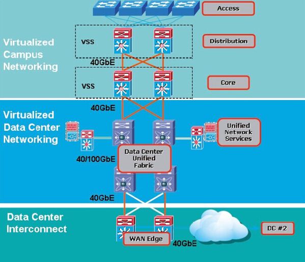
40/100GbE is rapidly gaining traction as a key foundation for building the next generation of virtualized data center and campus environments. The 40/100GbE-based architecture for virtualized data center and campus is illustrated in the paper. IT managers are increasingly aware of the benefits and advantages1 offered by 40/100GbE as well as its promise as an interconnect option among data centers and commercial buildings in the campus.

On the economic side, barriers to entry in the 40/100GbE space continue to fall. Capital investment in 10GbE networks today can be protected when upgrading to 40/100GbE networks in the future. The Ethernet switching and fiber cabling examples in this paper illustrate:

• 55 percent2 of on switching equipment can be protected

• 57 percent3 of investment on fiber cabling can be preserved

On the availability side, more vendors have supplied solutions for the 40/100GbE ecosystem, and a number of multi-vendor interoperability events on 40/100GbE technology have been hosted by the Ethernet Alliance? With both Cisco? and CommScope? Actively participating. So, early adoption anxieties over locked-in vendor relationships have evaporated. The greater availability from multiple vendors and declining deployment costs due to broader adoption in the marketplace make 40/100GbE infrastructure a sound and prudent investment, both for today and tomorrow.

The increased traction of 40/100GbE has led to its best practice status as the standard for the next generation of high-bandwidth virtualized applications. This adoption has been fueled by both its superior performance and economic benefits in virtualized environments.

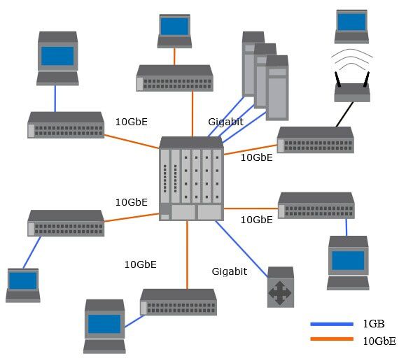
40/100GbE based architecture for virtualized Data Center and campus

40-100GbE-based-architecture-for-virtualized-Data-Center-.jpg

Virtualized Data Center

True data center virtualization is end-to-end virtualization, including server virtualization, storage virtualization, and network virtualization, and can result in many diverse benefits. Virtual machines and networks can be quickly and nimbly deployed. Their energy efficiency and capacity can dynamically scale to meet the demands of variable workloads without wasting resources. Disaster recovery is faster, and both initial and ongoing costs can be lower than those of traditional non-virtualized approaches.

In the journey to the virtualized data center and cloud, data center managers face a number of design and operational challenges. One of the most conspicuous challenges for network design is to provide enough bandwidth for the applications of today and the foreseeable future. With converged network technologies, 10GbE, which is becoming a de facto choice for server access networks, can be a good choice for a storage access network as well. Given 10GbE at the access layer, 40/100GbE is recommended for aggregation and core layers of networks in data centers, and this is where 40/100GbE removes the constraints that have previously prevented virtualized data centers from fulfilling their maximum potential.
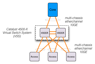
 

Virtualized Campus

Video is a strongly growing application in campus networks. Video applications are more than just video conferencing or video streaming. Enterprise video applications include desktop high definition video, video phone, enterprise TV, IP video surveillance and other video generation and sharing. Bring your own device (BYOD) is another emerging trend in the campus network. Video, voice, data and BYOD put pressure on a campus’s distribution and core networks.

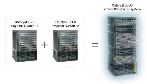
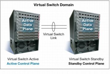
Compared to traditional layer 2 and 3 network design in the campus, the core and distribution networks can be virtualized by using Virtual Switching System (VSS) with Cisco Catalyst 6500 series switches. VSS is a network system virtualization technology that pools two or more Cisco Catalyst 6500 Series Switches into a virtual one. A VSS scales system bandwidth capacity with automatic load sharing. A VSS increases operational efficiency by simplifying the network and reducing switch management overhead by at least 50 percent. A VSS boosts nonstop communications with no disruption to applications. A VSS enhances existing multilayer switching architecture without fundamentally changing the architecture, resulting in ease of adoption and migration of the technology.
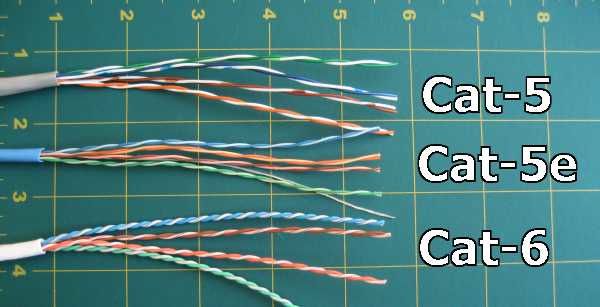
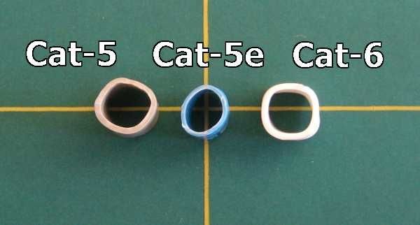
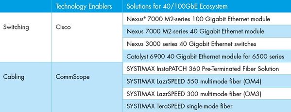
 

Ecosystem

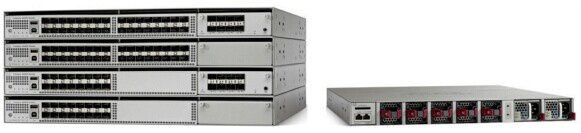
A list of examples of 40/100GbE Ethernet switching and cabling solutions from Cisco and CommScope.

40/100GbE ecosystem examples

 40-100GbE-Ecosystem-Examples.jpg

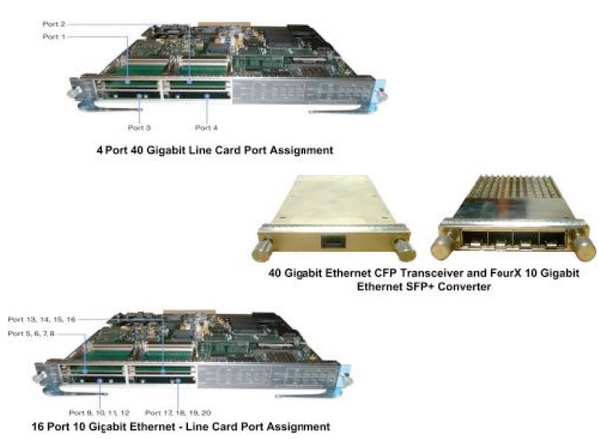
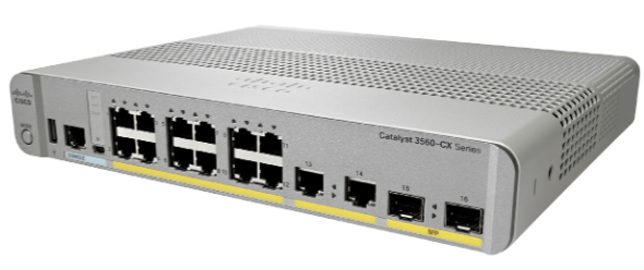
The new Cisco Catalyst 6900 Series 4-Port 40GbE Fiber Module (WS-X6904-40G) for the Cisco Catalyst 6500 Series Switches was developed for deployment in the enterprise campus distribution layer and core layer, in traditional data centers with 10 Gigabit aggregation, and in metro-Ethernet-based data center interconnections, as well as in multipurpose service provider networks, which require high-performance data throughput coupled with security, manageability, virtualization, and quality of service.

The WS-X6904-40G module supports 10GbE and 40GbE interfaces. Figure 2 shows the 10GbE and 40GbE interfaces of Cisco Catalyst 6500 series switches. This new module is the only solution that supports both connections in a single format, for flexible migration. There are also many other new and exciting capabilities unique to the WS X6904-40G module, such as CTS (Cisco Trust Sec) for end-to-end role-based security deployment using SGT (Security Group Tagging) and SGACL (Security Group Access Control List) and link-by-link encryption based on IEEE 802.1AE MACsec (MAC based Security) standard, VNTag (Virtual Network Tag), and extensive quality of services features. The 40GbE Fiber Module is a perfect choice for forming a campus core network by interconnecting the physical switches of a VSS in core/distribution layer networks in the campus. It also can be utilized to connect access switches to a VSS at the distribution layer of the campus network. Users are deploying this module today and using it for four 10GbE links until they really need a true 40GbE channel.

Cisco Catalyst 10GbE and 40GbE Fiber Modules and optical transceivers

10GbE-and-40GbE-interfaces-of-Cisco-Catalyst-6500-series-sw.png

CommScope SYSTIMAX? InstaPATCH? 360 Pre-Terminated Fiber Solutions enable network operations in the data center at the current 10GbE speed of today, while provisioning for eventual upgrades to 40GbE and/or 100GbE. These solutions were tested, qualified and demonstrated in multi-vendor closed-door and open-to-public environments at both transceiver and system levels.4 Results repeatedly demonstrated that the performance of InstaPATCH 360 Pre-Terminated Fiber Solutions and LazrSPEED? Multimode fiber solutions far exceed the cable reach specified in IEEE Std. 802.3baTM-2010, “40 and 100 Gigabit Ethernet” standards.

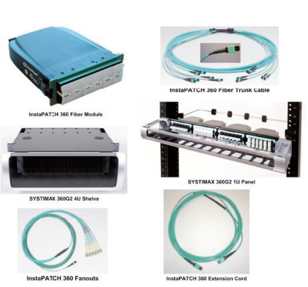
SYSTIMAX InstaPATCH 360 Pre-Terminated Fiber Solutions utilize the standard Method B polarity scheme. Customers who have chosen the fiber solution have invested in high-performance and high-quality fiber solutions, but also have purchased peace of mind: their data center fiber cabling infrastructure is ready for 40/100GbE whenever and wherever they need it. The eventual upgrade can be a simple and painless process. Figure 3 shows samples of SYSTIMAX InstaPATCH 360 Pre-Terminated Fiber Solutions.

Samples of SYSTIMAX InstaPATCH 360 Pre-Terminated Fiber Solution

Samples-of-SYSTIMAX-InstaPATCH-360-Pre-Terminated-Fiber-Sol.png


Solutions Designed to Maximize Return on Investment

The switching solutions from Cisco and cabling solutions from CommScope enable easy adoption of 10GbE today and seamless upgrades to 40/100GbE in the future.

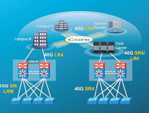
The Cisco Catalyst 6500 E-Series chassis, 6900 series 10GbE and 40GbE modules, and Supervisor T2 module provide the easy upgrades. End users’ investment protection can be achieved by redeploying the common components. The common switching components may include a Catalyst 6500 E-Series chassis, a supervisor module Sup2T, and two power supplies. As illustrated in the example in Figure 4, end users can save 55 percent1 of capital expense on the common components for 40GbE short reach (SR), or 47 percent1 of expenses for 40GbE long reach (LR) when upgrading from 10GbE.

40GbE deployment in campus

40GbE-deployment-in-campus.jpg

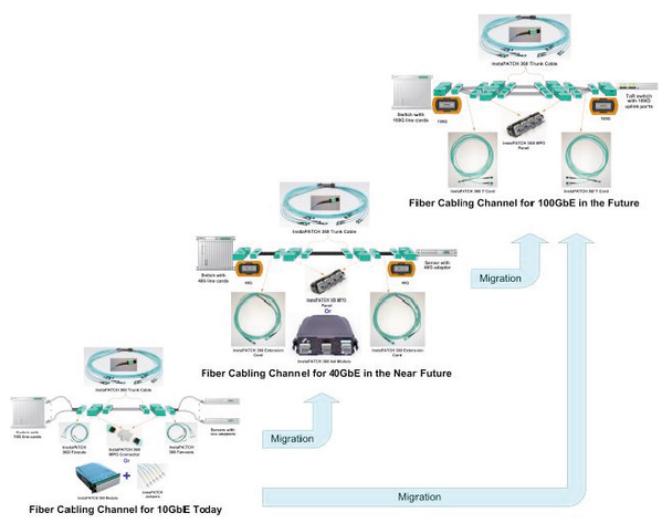
Similarly, CommScope SYSTIMAX InstaPATCH 360 Pre-Terminated Fiber Solutions offer seamless migration from 10GbE to 40/100GbE with investment preservation. A typical preterminated multimode fiber cabling channel is composed of components such as apparatus, patch cord, patch panel or shelf, and Multi-Fiber Push On (MPO) trunk cable. Figure 5 illustrates the fiber cabling channel for 10, 40 and 10 Gigabit Ethernet link, respectively. It’s noticeable that the common cabling component among the three channels in Figure 5 is the pre-terminated fiber trunk cable. Figure 5 also provides a cabling infrastructure migration path from 10GbE today to 40 or 100GbE in the future.

Fiber cabling migrations from 10GbE to 40/100GbE

Fiber-cabling-migrations-from-10GbE-to-40-100GbE.png

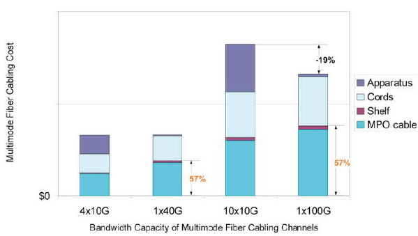
Each physical Ethernet link has one cabling channel. The cabling cost of four 10GbE links (or channels), one 40GbE link, ten 10GbE links and one 100GbE. The cost is the result of adding the costs of all the cabling components and then dividing the sum by the number of Ethernet links (or cabling channels) for each corresponding speed.

The investment preservation example5 on pre-terminated fiber cabling

The-investment-preservation-example5-on-pre-terminated-fibe.png

With the reuse of the common cabling components—which are the SYSTIMAX InstaPATCH 360 Trunk Cable and 360G2-1U Modular Shelf in this example—end users can save 57 percent2 of the capital expense on multimode fiber cabling when migrating from today’s 10GbE to either 40GbE or 100GbE in the future.

The costs for 4x10G and 10x10G fiber cabling are denoted in Figure 6 for a rough reference to their corresponding counterparts of 40 and 100GbE, respectively. The fiber cabling cost for 1x40G is close to the one for 4x10G, while the 1x100G cost is 19 percent less than the one for 10x10G’s cost, in this example.

You may be wondering why the cost of the MPO cable increases when migrating from 4x10G to 1x40G and from 10x10G to 1x100G. This is because, as there are unused fibers, only a fraction of the trunk cost is allocated to the 10GbE scenarios; but for the 40G and 100G scenarios, the total trunk cost is allocated. In other words, only four out of six possible fiber circuits are lit in the 4x10G case, so only 4/6ths of the cost is applied. Similarly, only 10 out of 12 possible fiber circuits are lit in the 10x10G case so only 10/12ths of the cost is applied. Notice that the 57 percent investment preservation on fiber is not the only saving for end users.

When the distribution and core layer networks migrate to 40/100GbE, the apparatus and cords can be reused in other parts of the networks: for example, the access layer network for 10GbE or even Fibre Channel SAN networks. By doing so, end users may preserve more of their investment.

The ongoing adoption of 40/100GbE is already redefining the IT landscape. It represents the first step toward the next generation of high-bandwidth connectivity demanded by virtualized data centers and campuses. As 40/100GbE continues to unlock the full performance and economic potential of virtualized environments and more campus deployments, it will undoubtedly solidify its position as the new standard for best practice, speed and reliability.

Because it affords instant benefits as well as a streamlined upgrade path, forward-looking IT managers would be well advised to include 40/100GbE as a key part of any upgrade or new deployment plans, particularly those that include a need for campus-wide interconnectivity between data centers, and inside data centers and office buildings. In particular, Cisco Catalyst 6500 series switches with their 40GbE fiber module and CommScope SYSTIMAX InstaPATCH 360 pre-terminated, LazrSPEED and TeraSPEED? fiber solutions deliver the performance and reliability that position today’ s investment for rich returns in the future.

References and Notes

1. G. Chanda from Cisco and Y. Yang from CommScope, “40 GbE: What, Why & Its Market Potential”, Ethernet Alliance white paper, November, 2010

2. The two percentages can vary based on a number of factors, such as hardware configurations, purchasing prices, etc. The new installation must be tested and meet the specifications issued by Cisco Systems.

3. The percentage can vary based on a number of factors, such as MPO trunk cable length, cabling channel configurations, purchasing prices, etc. The new installation must be tested and meet the specifications issued by CommScope SYSTIMAX.

4. D. Hall and Y. Yang from CommScope, “40/100 Gigabit Ethernet Eco-System is Alive and Well”, CommScope white paper, 2011

5. In the example of Figure 6, the MPO trunk cable length is 174 feet and the cord length is 10 feet. These lengths are determined based on Paul Kolesar’s contribution to IEEE 802.3 Next Gen 40G and 100G Optics Study Group in May 2012, “Cabling Cost-Centroid Lengths for Simplified Total Cost Comparisons”.

The multimode fiber cabling channel configuration for the example in Figure 6 is an interconnect configuration. In the 10GbE cabling channels, two fiber modules are connected back to back by MPO trunk cables, and LC jumpers are plugged in to connect the fiber modules at both ends. In the 40/100GbE cabling channels, two MPO adapter panels are connected back to back by an MPO trunk cable, and equipment cords are plugged into MPO adapter panels at both ends.

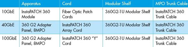
The following table lists the products used in the cost study for the investment preservation example5 on pre-terminated fiber cabling

the-products-used-in-the-cost-study-for-the-investm-copy-1.jpg


More Network Topics

Cisco Intercloud Fabric for Providers & Business

What are the Considerations While Buying a Cisco Next-Generation Firewall?

Selecting Cisco Switches, For Campus or Branch?

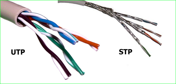
10GBASE-T or SFP Plus

What Items You Need When Ordering a Cisco Aironet 1530 Outdoor AP?

$
0
0

If you want to order a Cisco Aironet 1530, do you know what basic item you will get?

The body access point, power supply, Antennas, and software….That’s not enough.

 A fully operational system requires at least the following items: Access point, Power source, Antennas: 2.4 GHz, 5 GHz, or dual band (Cisco Aironet 1532E Outdoor Access Point only), Mounting bracket, Software selection.

Cisco-Aironet-1530-AP.jpg

Note that accessories are available as configurable options and as spares. An equal sign (=) at the end of the part number indicates that the part is a spare: for example, AIR-PWRINJ1500-2=.

Basically, the Cisco Aironet 1530 Series is available in two models:

● Cisco Aironet 1532I (internal antennas): The Cisco Aironet 1532I Outdoor Access Point is a low-profile, lightweight model in the Cisco Aironet 1530 Series. The smaller size and sleeker look helps it blend in with the surrounding environment. The Cisco Aironet 1532I access points are dual-radio systems with internal antennas and comply with IEEE 802.11b/g/n (2.4 GHz) and 802.11a/n (5 GHz) standards. The 2.4-GHz radio is a 3x3 multiple-input and multiple-output (MIMO) radio that supports up to three spatial streams. The 5-GHz radio is a 2x3 MIMO radio that supports two spatial streams.

● Cisco Aironet 1532E (external antennas): The Cisco Aironet 1532E Outdoor Access Point is also a low-profile and lightweight model, but it supports a flexible radio coverage area through the use of external antennas. With the unique Cisco Flexible Antenna Port technology, the antenna ports can be software configured for dual-band or single-band operation.

Cisco Aironet 1530 Series Models

Part Number

Description

AIR-CAP1532I-x-K9

802.11n Low-Profile Outdoor AP, Internal Ant., x Reg Dom.

AIR-CAP1532E-x-K9

802.11n Low-Profile Outdoor AP, External Ant., x Reg Dom.

In Table above, “x” is a placeholder for the regulatory domain designator. Please see http://www.cisco.com/go/aironet/compliance to determine which regulatory domain is used in your country. Note that the regulatory domain used in your country might differ depending on access point model and that some models are not available for all countries.

The following items are included with every model:

● Access point

● Grounding lug

● DC power connector

● One liquid-tight adapter for sealing the cable ingress connection

● Sealant for the antenna connections

● Antiseizing compound for the mounting brackets


In the following part, we will introduce each item of a Cisco Aironet 1530 Series that is required in your deployment.

Network Connection

The Cisco Aironet 1530 Series access points can connect to the network wirelessly or through a wired Ethernet connection.

● Wireless: An access point that connects to the network through another access point over a wireless backhaul is known as a mesh access point (MAP). The backhaul radio is built in, and no wired connection is needed for MAPs. An access point that acts as the gateway for mesh nodes is known as a root access point (RAP). RAPs connect to the network through a wired Ethernet connection. In these cases, a liquid-tight adapter is provided with the access point to seal the cable entry.

● Ethernet: The Cisco Aironet 1530 Series supports 10/100/1000 Gigabit Ethernet using a shielded RJ-45 connector with minimum Category 5 cable. Please see your local supplier for an outdoor-rated cable and shielded connectors.


Power

Powering Options for the Cisco Aironet 1530 Series

Part Number

AC

DC

Power over Ethernet (PoE)

AIR-CAP1532I-x-K9

AC/DC adapter

24-57 VDC

UPoE or PoE+(802.3at)*

AIR-CAP1532E-x-K9

AC/DC adapter

24-57 VDC

PoE+(802.3at)

*When the Cisco Aironet 1532I is powered using Enhanced PoE (PoE+) power, the access point will automatically disable one of the 2.4-GHz transmitters.

AC Power

To power the Cisco Aironet 1530 Series from an AC power source, an external AC/DC power adapter is required. When powering the Cisco Aironet 1530 Series from streetlight power, please note that the maximum voltage is 277 VAC and requires the power adapter and the street light tap. The following lists the power adapter and tap part numbers.

AC/DC Power Adapter and Streetlight Tap

Part Number

Description

AIR-PWRADPT-1530=

Power Adapter (AC/DC) - Outdoor AP1530 Series

AIR-PWRADPT2-1530=

Power Adapter (AC/DC) - Outdoor AP1530 Series, for Japan only

AIR-PWR-ST-LT-R3P=

Power cord, 4 ft, Streetlight Tap

Power over Ethernet

The Cisco Aironet 1530 Series can be powered over the Ethernet connection. Power can be sourced directly from an appropriately powered switch port or from an inline power injector. The approved power injectors are listed in Table 4.

Power Injector for Use with Power over Ethernet

Part Number

Description

AIR-PWRINJ1500-2=

1520/1550/1530 Series Power Injector

AIR-PWRINJ-30=

Power Injector - 30W for AP1530 - Spare

You must also specify the country type power cord for the power injector. The AIR-PWRINJ1500-2= and AIR-PWRINJ-30= power injectors are for indoor environments only.

The Cisco Aironet 1530 Series access points use a standard RJ-45 Ethernet connector. Cisco does not provide an Ethernet cable for the Cisco Aironet 1530 Series. You will need to source an outdoor-rated, Category 5 or better Ethernet cable and shielded RJ-45 connectors from a local supplier. A liquid-tight gland is provided with the access point to seal this cable entry point from weather.

DC Power

The Cisco Aironet 1530 Series access points support power from an external 24 to 57 VDC power supply with a minimum of 30 watts (W). A terminal block is included with your access point for this purpose, with liquid-tight adapter to weatherproof the connection. When using DC power, please consult the hardware installation guide for instructions on how to correctly assemble the connector.

The Cisco Aironet 1530 Series can be installed with redundant power sources. When multiple power sources are available, the access point will use power in the following priority: DC power & PoE

Antennas

The Cisco Aironet 1532E access points are equipped with a combination of radios operating in the 2.4- and 5-GHz bands. Both radios can support two transmit and two receive streams using Maximal Ratio Combining (MRC), which takes advantage of multipath signals received across the two antennas to improve signal quality.

The table below describes the antennas available for the Cisco Aironet 1532E access points, listing part numbers for the antennas as well as gain and other details.

Antennas for the Cisco Aironet 1532E Access Point

Part Number

Frequency Band

Gain

Type

Required Quantity

AIR-ANT2547VG-N

2.4/5 GHz

4/7 dBi

Omnidirectional

2

AIR-ANT2547V-N

2.4/5 GHz

4/7 dBi

Omnidirectional

2

AIR-ANT2588P3M-N=

2.4/5 GHz

8/8 dBi

Directional

1

AIR-ANT2450V-N

2.4 GHz

5 dBi

Omnidirectional

2

AIR-ANT2480V-N

2.4 GHz

8 dBi

Omnidirectional

2

AIR-ANT2413P2M-N=

2.4 GHz

13 dBi

Directional

1

AIR-ANT5180V-N

5 GHz

8 dBi

Omnidirectional

2

AIR-ANT5114P2M-N=

5 GHz

14 dBi

Directional

1

For additional antenna specifications, see the Cisco Aironet Antenna and Accessories Reference Guide.

The access points are provided with a moldable sealant to protect the antenna connector from weather. Consult the installation guide for proper installation.

Lightning Arrestors

When you use cables between the antenna and the Cisco Aironet 1532E access point, Cisco recommends that you add lightning arrestors to each port, particularly when the deployment is in an area with high lightning activity. The lightning arrestor listed in Table 6 provides robust protection against induced currents in the RF cabling generated by nearby lightning strikes.

Note: The lightning arrestor does not protect against direct lightning strikes on the access point.

Lightning Arrestor for the Cisco Aironet 1530 Series

Part Number

Description

AIR-ACC245LA-N=

2.4 and 5 GHz Lightning Arrestor, N Connector


Mounting Brackets

Cisco Aironet 1530 Series outdoor access points can be mounted on poles or walls. The standard vertical, pole-mounting brackets can be ordered as an option or as a spare. The mounting brackets with tilt mechanism can be ordered separately as a spare.

Mounting Brackets for the Cisco Aironet 1530 Series

Part Number

Description

AIR-ACC1530-PMK1 (=)

Standard Pole/Wall Mount Kit for AP1530 Series

AIR-ACC1530-PMK2=

Pole Mount Kit for AP1530 Series with Tilt Adjustment

Both pole-mount kits include two sets of stainless-steel bands to fit poles from 2 to 8 inches in diameter. For larger poles, consult a local provider.


Software Requirements

The Cisco Aironet 1530 Series requires the minimum software releases noted in the following table.

Minimum Software Releases

Part Number

Minimum Software Release

AIR-CAP1532I-x-K9

Software Release 7.6 or later

AIR-CAP1532E-x-K9

Software Release 7.6 or later

Additional functions are available for the access points with more recent releases. Please see the applicable release notes for more information about features available with newer releases.

Software Ordering Option

Cisco Aironet 1530 Series access points can be deployed in unified or autonomous mode. The access point boots in the default mesh mode and can reboot in autonomous mode with a command-line interface (CLI) command. Both unified and autonomous images are included in the software part number in Table 9.

Software Option for Cisco Aironet 1530 Series

Part Number

Description

SWAP1530-CMB-A1-K9

1530 Series Combined Unified and Autonomous SW


Optional Items

Cover and Solar Shield

Cisco 1530 Series outdoor access points can be deployed with an optional paintable cover to enable the access point to blend into the surroundings.

Accessory Kit

Additional cable glands and other spare items are available in an accessory kit (Table 10). This kit contains the following items:

● 10 cable glands

● 1 console port cover

● 2 Ethernet and power port covers

● 1 DC power connector

● 1 ground lug and screws

Cisco Aironet 1530 Series Accessories

Part Number

Description

AIR-ACC1530-CVR=

Cover and Solar Shield for AP1530 Series

AIR-ACC1530-KIT1=

Spare accessory kit for AP1530 Series

If you want to place an order of Cisco Aironet 1530, you can consult router-switch.com’s representative for additional assistance in ordering mesh and other Cisco networking equipment.


More Related Cisco Access Points

Cisco Aironet 1530 Series Outdoor Access Point-Features & Models

Cisco Aironet 1552E/EU vs. Aironet 1552C/CU vs.1552I vs.1552H Outdoor Points

Bundled Systems for Cisco 4000 Series ISRs Ordering Guide

$
0
0

Designed to help branch and remote offices do more with less, the Cisco 4000 Series also can be ordered as prepackaged bundled systems for deploying advanced technologies, such as security, unified communications, and application services in the branch office. So in the following part we will talk about the main ordering information of Security Bundles, AX Bundles, and AXV Bundles.

Security Bundles

Cisco router security bundles deliver powerful security features, such as Cisco IOS Software Zone-Based Firewall, VPN, and infrastructure security services over numerous WAN access technologies, providing high levels of performance, scalability, and availability to meet today's growing business requirements. The following Table lists the security bundle for the Cisco 4000 Series ISRs that ship with the Security technology license activated and the advanced security features available for use. By default, this bundle ships with the universal Cisco IOS Software image that supports payload cryptography.

Security Bundle for Cisco 4000 Series ISRs (Includes universalk9 Image and Security License)

Part Number

Description

Technical Service Part Number
(SMARTnet 8x5xNBD*)

ISR4451-X-SEC/K9

Cisco ISR 4451 Security Bundle w/SEC license

CON-SNT-ISX451-X

ISR4431-SEC/K9

Cisco ISR 4431 Security Bundle w/SEC license

CON-SNT-CISCO 4431 ISRCISCO 4431 ISRS

ISR4351-SEC/K9

Cisco ISR 4351 Security Bundle w/SEC license

CON-SNT-ISR4351S

ISR4331-SEC/K9

Cisco ISR 4331 Security Bundle w/SEC license

CON-SNT-ISR4331S

ISR4321-SEC/K9

Cisco ISR 4321 Security Bundle w/SEC license

CON-SNT-ISR4321S

* 8x5xNBD service is delivered 8 hours a day, 5 days a week (weekdays), by next business day.

Unified Communications Bundles

The Cisco 4000 Series ISR voice bundles enable unified communications through a comprehensive signaling and media-processing infrastructure. It includes a variety of protocols, media interworking, signal and media security, transcoding, conferencing, and quality-of-service (QoS) capabilities. You can order these bundles with optional licenses for SRST.

The Unified Communications bundles (except ISR 4321) include the new Cisco Packet Voice DSP Module 4 (PVDM4), which has been optimized for concurrent voice support. The PVDM4 modules support all voice gateway functions of earlier generations of PVDMs.

The table below lists the voice bundle for Cisco 4000 routers that comes with PVDM4, UC technology license, and the unified communications features available for use. By default, this bundle ships with the universal Cisco IOS Software image that supports payload cryptography.

Unified Communications (UC) Bundles for the Cisco 4000 Series ISR Family (Includes universalk9 image, Unified Communications License, and Cisco PVDM4)

Part Number

Description

Technical Service SKU
(SMARTnet 8x5xNBD*)

ISR4451-X-V/K9

Cisco ISR 4451 UC Bundle, PVDM4-64 w/ UC License

CON-SNT-ISR4451-X

ISR4431-V/K9

Cisco ISR 4431 UC Bundle, PVDM4-64, UC License

CON-SNT-ISR4431V

ISR4351-V/K9

Cisco ISR 4351 UC Bundle, PVDM4-64, UC License

CON-SNT-ISR4351V

ISR4331-V/K9

Cisco ISR 4331 UC Bundle, PVDM4-32, UC License

CON-SNT-ISR4331V

ISR4321-V/K9

Cisco ISR 4321 UC Bundle, UC License

CON-SNT-ISR4321V

* 8x5xNBD service is delivered 8 hours a day, 5 days a week (weekdays), by next business day.

The bundles ship with a UC and Security (SEC) technology license and unified communications features available for use. By default, the bundles ship with the universal Cisco IOS Software image that supports payload cryptography.

Voice Security Bundles for Cisco 4000 ISR Family Routers (Include universalk9 image, UC and SEC License, and Cisco PVDM4)

Part Number

Description

Technical Service Part Number
(SMARTnet 8x5xNBD*)

ISR4451-X-VSEC/K9

Cisco ISR 4451 Voice Sec. Bundle, PVDM4-64 w/ UC and SEC License PAK

CON-SNT-ISR41-X

ISR4431- VSEC/K9

Cisco ISR 4431 Voice Sec. Bundle, PVDM4-64 w/ UC and SEC License PAK

CON-SNT-ISR44SEC

ISR4351-VSEC/K9

Cisco ISR 4351 VSEC Bundle, PVDM4-64 w/ UC, SEC Lic, CUBE-25

CON-SNT-ISR4351VS

ISR4331-VSEC/K9

Cisco ISR 4331 VSEC Bundle, PVDM4-32 w/ UC, SEC Lic, CUBE-10

CON-SNT-ISR4331VS

ISR4321-VSEC/K9

Cisco ISR 4321 VSEC Bundle, w/ UC, SEC Lic, CUBE-10

CON-SNT-ISR4321VS

* 8x5xNBD service is delivered 8 hours a day, 5 days a week (weekdays), by next business day.

Information about the Cisco 4000 Series ISR Application Experience Bundle is available in the Cisco Application Experience (AX) ordering guide.

AX Bundles

Cisco router AX bundles deliver a combination of security features along with Cisco Wide Area Application Services (WAAS) features. The security features include the Cisco IOS Software Zone-Based Firewall, VPN, and infrastructure security services over numerous WAN access technologies. The WAAS features include Application Visibility and Control (AVC), Cisco Performance Routing (PFRv3), and application optimization. The Table below lists the AX bundle for Cisco 4000 Series ISRs that comes with the security technology and the WAAS license activated. By default, this bundle ships with the universal Cisco IOS Software image that supports payload cryptography.

AX Bundle for Cisco 4000 (Includes universalk9 Image, WAAS, and Security License)

Part Number

Description

Technical Service Part Number
(SMARTnet 8x5xNBD*)

ISR4451-X-AX/K9

Cisco ISR 4451 AX Bundle w/APP, SEC license

CON-SNT-ISR4X51-X

ISR4431-AX/K9

Cisco ISR 4431 AX Bundle w/APP, SEC license

CON-SNT-ISR4431A

ISR4351-AX/K9

Cisco ISR 4351 AX Bundle w/APP, SEC license

CON-SNT-ISR4351AX

ISR4331-AX/K9

Cisco ISR 4331 AX Bundle w/APP, SEC license

CON-SNT-ISR4331AX

ISR4321-AX/K9

Cisco ISR 4321 AX Bundle w/APP, SEC license

CON-SNT-ISR4321AX

* 8x5xNBD service is delivered 8 hours a day, 5 days a week (weekdays), by next business day.


AXV Bundles

Cisco router AXV bundles deliver a combination of security features along with Cisco Unified Communications (UC) and Cisco WAAS. The security features include the Cisco IOS Software Zone-Based Firewall, VPN, and infrastructure security services over numerous WAN access technologies, offering high levels of performance, scalability, and availability to meet today's growing business requirements. The WAAS features include Application Visibility and Control (AVC), Cisco Performance Routing (PFRv3) and application optimization. The bundles also ship with a UC technology license, and unified communications features available for use.

The following table lists the AXV bundle for the Cisco 4000 Routers that come with the security, UC, and WAAS licenses activated. By default, this bundle ships with the universal Cisco IOS Software image that supports payload cryptography.

AXV Bundle for Cisco 4000 Series ISRs (Includes universalk9 Image, WAAS, and SEC License)

Part Number

Description

Technical Service Part Number
(SMARTnet 8x5xNBD*)

ISR4451-X-AXV/K9

Cisco ISR 4451 AXV Bundle w/APP, UC, PVDM4-64, SEC license

CON-SNT-ISR4451

ISR4431-AXV/K9

Cisco ISR 4431 AXV Bundle w/APP, UC, PVDM4-64, SEC license

CON-SNT-ISR4431AX

ISR4351-AXV/K9

Cisco ISR 4351 AXV Bundle w/APP, UC, PVDM4-64, SEC license

CON-SNT-ISR4351XV

ISR4331-AXV/K9

Cisco ISR 4331 AXV Bundle w/APP, UC, PVDM4-32, SEC license

CON-SNT-ISR4331XV

ISR4321-AXV/K9

Cisco ISR 4321 AXV Bundle w/APP, UC, SEC license

CON-SNT-ISR4321XV

* 8x5xNBD service is delivered 8 hours a day, 5 days a week (weekdays), by next business day.


Cisco and Partner Services for the Branch Office

Transform the branch-office experience and accelerate business innovation and growth using intelligent, personalized services from Cisco and our partners. We have the depth and breadth of expertise to create a clear, replicable, optimized branch-office footprint across technologies. Planning and design services align technology with business goals and can increase the accuracy, speed, and efficiency of deployment. Technical services help improve operational efficiency, save money, and mitigate risk. Optimization services are designed to continuously improve performance and help your team succeed with new technologies.

Technical Services Available for Cisco 4000 Series ISRs

● Cisco SMARTnet Services provide comprehensive technical support services for the Cisco 4000 Series ISRs (both base systems and bundled systems), Cisco IOS Software and feature licenses, and modules that include the Cisco Unified Computing System (Cisco UCS®) E-Series Module. Cisco SMARTnet Services include advance hardware replacement, OS updates, online tools and resources, and Cisco Technical Assistance Center (TAC) support.

● Cisco Application Support plus Upgrades (SASU) provides technical support services, including updates and upgrades for any Cisco software application running on the Cisco UCS E-Series Module.

The Cisco technical services use cases that match the system you buy.

If You Buy a Cisco 4000 Base or Bundled System with:

You Need:

Any Cisco IOS Software, including technology or feature licenses for Cisco IOS Software

Cisco SMARTnet Service

Any modules, including Cisco UCS E-Series Modules

Cisco SMARTnet Service

An application running on a Cisco UCS E-Series Module

Cisco SMARTnet Service + SASU

A security feature set and you do not require intrusion-prevention-system (IPS) signature updates

Cisco SMARTnet Service


Reference from  http://www.cisco.com/c/en/us/products/collateral/routers/4000-series-integrated-services-routers-isr/guide-c07-732797.html#_Toc407238273


More…

Cisco 4000 Series ISR, Top Choice for Today’s Branch Offices

Cisco 4451-X vs. Cisco 3945E vs. 3925E vs. Cisco 3945 vs. 3925 Router

Ordering Guide-Cisco 4400 and 4300 Series Routers/Cisco 4000 Router Family

Ordering Guide-Optional Items, IOS Software Images and Licenses for the Cisco 4000 Series ISR

Have a Look at Cisco Multigigabit Ethernet Switches

$
0
0

Multigigabit Ethernet Technology Supports New Intermediate Network Speeds

Multigigabit-Ethernet-Technology-Supports-New-Intermediate-.jpg


Benefits-Multigigabit Ethernet Technology

• Increase network bandwidth and speed without running multiple cables between switches and access points.

• Lower operational costs by getting more performance out of existing cabling infrastructure.

• Power devices that require up to 60W, at speeds over 1 Gbps, even at 10G Base-T rates.

Cisco-Catalyst-3560-CX-Compact-Switch-Deploy-in-a-Snap.jpg

Network needs are changing quickly. Thanks to evolving wireless standards and the rising number of wireless devices, keeping up with data rates and growing traffic can be a challenge. Your traditional Ethernet infrastructure can support speeds up to 1 Gigabit per second (Gbps), but competing today requires much more capacity. One option is completely replacing your legacy cabling infrastructure and upgrading your hardware. But wouldn’t it be better to increase network speed and traffic capacity in a way that’s quick, inexpensive, and efficient?


Cisco’s new Multigigabit Ethernet switches offer just that: an easy-to-deploy, budget-friendly solution that allows you to increase network speed and bandwidth using your existing cables. By partnering with other industry leaders to form the NBASE-T Alliance, Cisco uses NBASE-T technology to help you get more out of your existing infrastructure. Save time and money by avoiding upgrades and extending the life of your installed cable plants. And discover the benefits of meeting consumer demand for increased bandwidth and speeds without a large initial investment.

Multigigabit Ethernet technology uses capabilities in your existing cabling infrastructure to meet bandwidth requirements and provide up to five times the performance. The technology enables intermediate data rates of 2.5 and 5 Gbps to ease the jump between traditional rates of 1 Gbps  and 10 Gbps. These intermediate rates run on the majority of installed cables and preserve legacy UTP wiring, which is good for 802.11ac wireless LAN applications.

The technology also supports Power over Ethernet (PoE) forms, including PoE+ and UPOE. Cisco Multigigabit Ethernet switches help you avoid having to run multiple cables between switches and access points and let your networks welcome next-generation traffic speeds and data rates.

As part of our next-generation architecture, Multigigabit Ethernet switches will be supported on multiple Cisco Catalyst platforms:

• Cisco Catalyst 4500E Series Switches: Multigigabit Ethernet technology will be introduced in the form of a new E-Series line card compatible with Supervisor Engine 8-E and beyond.

• Cisco Catalyst 3850 Series Switches: New 24-port and 48-port switches will support Multigigabit technology.

• Cisco Catalyst Compact Switches: A new 8-port switch will support Multigigabit technology.

More about Cisco’s New Compact Switch-Catalyst 3560-CX and 2960-CX Series

Have-a-Look-at-Cisco-Multigigabit-Ethernet-Switches.jpg

An effective work environment encourages collaboration. That often means tearing down office walls to create open workspaces. Doing that is now simpler and less costly, thanks to Cisco’s next generation of compact switches, the Cisco Catalyst 3560-CX and 2960-CX Series.

With their quiet, fan-less design, the switches create many possibilities for designing workspaces. They can reside nearly anywhere outside your wiring closet. Install them in carpeted areas such as offices, conference rooms, classrooms, and retail stores for quick, flexible connections. Rearrange rooms and floors without changing your cabling infrastructure.

Cisco Catalyst 3560-CX Compact Switch

Deploy in a Snap

• Transform your workspaces without cabling hassles and expenses

• Locate switches nearly anywhere, outside your wiring closet

• Deploy Internet of Things (IoT) devices in your enterprise

• Replace your hubs, simplify switch management, and enhance security

• Aggregate gigabit Wi-Fi traffic flows with 10-Gbps uplinks

Cisco-Catalyst-3560-CX-Compact-Switch.png

Consolidate cabling for big savings. Rather than running multiple Ethernet cables from endpoints like IP phones and Wi-Fi access points to a wiring closet, you just connect devices over a few feet of cabling to a nearby 3560-CX or 2960-CX switch. Then connect the compact switch to the wiring closet with a single Ethernet or fiber cable. Using this setup, a 200-room hotel using compact switches in guest rooms can eliminate up to 30 kilometers of cables. And a five-story shopping complex can eliminate about 7.5 kilometers of cable.

Note: 4:1 consolidation of cables, cable reduction of 3x100m for each customer service station. Assume 10 customer service stations per floor. Assume average cable run is 50m across all customer service stations, leads to 300m * 50 * 0.5 = 7,500m total cable reduction.

The Cisco Catalyst 3560-CX and 2960-CX switches enable you to bring sensors, LED lights, building controllers, and other IoT devices onto the network using Power over Ethernet (PoE). The many features and controls offered by these PoE switches make them run more efficiently and reliably. For example, Cisco Perpetual PoE continues powering endpoints even during a switch boot, maximizing uptime. So there’s no need for backup power. The switches provide up to 240 watts of power for PoE devices − twice the capacity of current switches.

For simplified management, these switches have the option to run in Cisco Instant Access mode. Instant Access provides a single point of operation and management for your campus networks. And they support Cisco Plug and Play (PnP) technology, which automates network device deployments.

The Cisco Catalyst compact switches support the full suite of Cisco Catalyst feature set for enterprise-class security and reliability. Cisco TrustSec and other advanced access control features protect against man-in-the-middle attacks and keep your Cisco Catalyst environment secure.


More Related Cisco Multigigabit Ethernet Switch Topics

About Cisco Catalyst Multigigabit Ethernet & Cisco Multigigabit Ethernet Switches

The Time of Multigigabit, Cisco’ s New Campus LAN Switches

New Cisco Catalyst 3560-CX and 2960-CX Series Switches Review

CAT-5, CAT-5e, CAT-6, and CAT-7-General Questions

Cat5e and Cat6 Cabling for More Bandwidth? CAT5 vs. CAT5e vs. CAT6

Cisco 4000 Series Integrated Services Routers-Series Comparison

$
0
0

Cisco users may have a general impression on the Cisco 4000 family. We also talked about the main features of Cisco 4000 ISR routers and the ordering guide. So in this article we will discuss the main model comparison of Cisco 4000 series that contains five platforms: the Cisco 4451, 4431, 4351, 4331, and 4321 ISRs, which differ primarily in performance capabilities and in the number of Network Interface Module (NIM) and Enhanced Service Module (SM-X) slots supported. What’s the main difference between these models? You can check the main table of Cisco 4000 model comparison.

Feature

4321

4331

4351

4431

4451

Form factor

1 rack unit (RU)
Desktop

1 RU

2 RU

1 RU

2 RU

Integrated WAN ports

1 GE / SFP
1 GE

1 GE / SFP
1 GE
1 SFP

2 PoE GE / SFP
1 GE/ SFP

2 PoE GE / SFP
2 GE / SFP

2 PoE GE / SFP
2 GE / SFP

Performance

50 Mbps
Upgradable to 100 Mbps

100 Mbps
Upgradable to 300 Mbps

200 Mbps
Upgradable to 400 Mbps

500 Mbps
Upgradeable to 1 Gbps

1 Gbps
Upgradable to 2 Gbps

Management port

1 GE (Integrated Out of Band)

Network Interface Modules (NIM)

2

2

3

3

3

Enhanced Services Module (SM-X)

N/A

1 single-wide

2 single- or
1 double-wide

N/A

2 single- or
1 double-wide

Integrated Services Card (ISC) slots

1
(PVDM 4)

1
(PVDM 4)

1
(PVDM 4)

1
(PVDM 4)

1
(PVDM 4)

USB ports (type A)

1

1

2

2

2

Default/max Flash

4 GB / 8 GB

4 GB / 16 GB

4 GB / 16 GB

8 GB / 32 GB

8 GB / 32 GB

Default/max DRAM

4 GB / 8 GB

4 GB / 16 GB

4 GB / 16 GB

4 GB / 16 GB

4 GB / 16 GB

Power supply type

External: AC, PoE

Internal: AC, PoE

Internal: AC, PoE or DC

Internal: AC, PoE or DC

Internal: AC, PoE or DC

Redundant power supply

No

No

No

Yes
Internal RPS

Yes
Internal RPS

Module online insertion and removal (OIR)

Yes

Yes

Yes

Yes

Yes

Server virtualization platform (UCS E-Series)

N/A

2-core single-wide,
4-core single-wide

2 core single-wide,
4 core single-wide,
4 core double-wide,
6 core double-wide,
8 core double-wide

N/A

2-core single-wide,
4-core single-wide,
4-core double-wide,
6-core double-wide,
8-core double-wide

Advanced Security

4321

4331

4351

4431

4451

Zone-based firewall and NAT services

VRF-Aware Firewall and Network Address Translation (NAT)

Hardware VPN acceleration 
(DES, 3DES, AES)

No

IPSEC VPN services

FlexVPN, Easy VPN remote server, Enhanced Easy VPN, Dynamic Multipoint VPN (DMVPN), 
Group Encrypted Transport VPN (GET VPN), V3PN, MPLS VPN

SSL VPN

No

Intrusion prevention

Yes

Network foundation protection

ACL, FPM, control plan protection, control plane policing (CoPP), QoS, role-based CLI access, source-based RTBH, uRPF, SSHv2

Cisco Cloud Web Security

Yes*

Identity-based networking

No

No

No

No

No

Cisco TrustSec

  • Security Group Tag Exchange Protocol (SXP), SGT over GETVPN
  • SGT over IPSEC
  • SGT over DMVPN
  • SGT-based ZBFW
  • Port/Layer 3 interface/IP/subnet-to-SGT mapping
  • SGT export in Flexible NetFlow

Unified Communications

4321

4331

4351

4431

4451

Local conferencing

Yes

Yes

Yes

Yes

Yes

Digital signal processor support

PVDM4

PVDM4

PVDM4

PVDM4

PVDM4

Cisco Unified Survivable Remote Site 
Telephony support

Up to 50

Up to 100

Up to 750

Up to 1200

Up to 2000

Cisco Unified Communications 
Manager Express support

Up to 50

Up to 100

Up to 250

Up to 350

Up to 450

Cisco Unity Express 
(NM, SM, or ISM)

Use Cisco Unity Connection on UCSE

Use Cisco Unity Connection on UCSE

Use Cisco Unity Connection on UCSE

Use Cisco Unity Connection on UCSE

Use Cisco Unity Connection on UCSE

Cisco Unified Border Element (CUBE)
(SIP/H.323 sessions)

100

400

1000

3000

6000

nano Cisco Unified Border Element (nanoCUBE)
(sessions)

N/A

N/A

N/A

N/A

N/A

Digital voice and video (T1/E1 channels)

Up to 240

Up to 360

Up to 720

Up to 720

Up to 1200

Analog/BRI voice

Up to 8 ports (FXS, FXO, E/M, BRi)

Up to 12 ports (FXS, FXO, E/M, BRi)

Up to 20 ports (FXS, FXO, E/M, BRi)

Up to 12 ports (FXS, FXO, E/M, BRi)

Up to 20 ports (FXS, FXO, E/M, BRi)

Routing and Multicast

4321

4331

4351

4431

4451

IPv4 routing protocols

RIP v1/v2, EIGRP, OSPF, BGP, PBR, PfR

RIP v1/v2, EIGRP, OSPF, BGP, PBR, PfR

RIP v1/v2, EIGRP, OSPF, BGP, PBR, PfR

RIP v1/v2, EIGRP, OSPF, BGP, PBR, PfR

RIP v1/v2, EIGRP, OSPF, BGP, PBR, PfR

Multicast routing protocols

PIM-SM, mroute (static route), and MLD

PIM-SM, mroute (static route), and MLD

PIM-SM, mroute (static route), and MLD

PIM-SM, mroute (static route), and MLD

PIM-SM, mroute (static route), and MLD

IPv6 routing protocols

EIGRP, RIP, OSPFv3, IS-IS, 
BGP and PBR

EIGRP, RIP, OSPFv3, IS-IS, 
BGP and PBR

EIGRP, RIP, OSPFv3, IS-IS, 
BGP and PBR

EIGRP, RIP, OSPFv3, IS-IS, 
BGP and PBR

EIGRP, RIP, OSPFv3, IS-IS, 
BGP and PBR

Wireless LAN

4321

4331

4351

4431

4451

Integrated 802.11 b/g/n access point

N/A

N/A

N/A

N/A

N/A

Integrated 802.11 a/b/g/n access point

N/A

N/A

N/A

N/A

N/A

Unified and autonomous mode

N/A

N/A

N/A

N/A

N/A

RP-TNC connectors for field-replaceable 
optional high-gain antennas

N/A

N/A

N/A

N/A

N/A

Diversity (dual antennas)

N/A

N/A

N/A

N/A

N/A

Wireless LAN controller module

Available on UCS E-Series

Available on UCS E-Series

Available on UCS E-Series

Available on UCS E-Series

Available on UCS E-Series

Wireless WAN

4321

4331

4351

4431

4451

3G /4G LTE cellular

Yes*

Outdoor antennas

N/A

N/A

N/A

N/A

N/A

Integrated Switching

4321

4331

4351

4431

4451

Maximum switched Ethernet ports

N/A

24

48

N/A

48

Maximum switched Ethernet LAN ports with PoE

N/A

24

48

N/A

48

PoE support (wattage) 
without PoE boost

120 W

250 W

500 W

250 W 
(with optional power supply redundancy)

500 W 
(with optional power supply redundancy)

PoE support (wattage)
with PoE boost

260 W

530 W

990 W

500 W 
(no power supply redundancy)

950 W 
(no power supply redundancy)

EtherSwitch Service Module type (width)

N/A

1 single

2 single or 1 double

N/A

2 single or 1 double

Application Services

4321

4331

4351

4431

4451

Intelligent Path Control

PfR

PfR

PfR

PfR

PfR

Network Contention Control

QoS, HQoS

QoS, HQoS

QoS, HQoS

QoS, HQoS

QoS, HQoS

Application Visibility

NBAR v2

NBAR v2

NBAR v2

NBAR v2

NBAR v2

WAN Optimization

ISR-WAAS

ISR-WAAS, 
vWAAS on UCS E-Series

ISR-WAAS, 
vWAAS on UCS E-Series

ISR-WAAS

ISR-WAAS, 
vWAAS on UCS E-Series

Akamai Connect

No

Yes

Yes

Yes

Yes

Cisco Application Centric Infrastructure

Application Policy Infrastructure Controller (APIC) with Enterprise Module

* Planned for 1H CY2015


More Related Topics to CISCO 4000 Routers

Ordering Guide-Cisco 4400 and 4300 Series Routers/Cisco 4000 Router Family

Ordering Guide-Optional Items, IOS Software Images and Licenses for the Cisco 4000 Series ISR

Cisco 4000 Series ISR, Top Choice for Today’s Branch Offices


Bundled Systems for Cisco 4000 Series ISRs Ordering Guide 

Viewing all 278 articles
Browse latest View live